

GW-7228 J1939/Modbus RTU Slave Gateway
User’s Manual (Ver 1.3, Apr/2011) ------------- 18
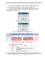
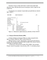
Table 2-3
:
LED indication of the GW-7228
LED Name
GW-7228 Status
LED Status
ALL LEDs
Firmware Updating Mode
All LED always turned on
Hardware WDT Fail
All LED blink per 1 second
Contact to ICP DAS
All LED blink per 100 ms
PWR LED
No Error
Always turned on
CAN Bus Transmission Fail Blink per 100 ms
CAN Bus-Off
Blink per 500 ms
Can
’t Claim Address in
J1939 Network
Blink per 1000 ms
Power Failure
Off
J1939 LED
Transmission
Blink
Bus Idle
Off
MODBUS
LED
Transmission
Blink
Bus Idle
Off
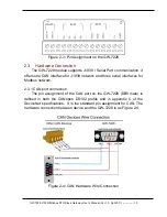
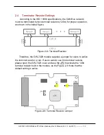
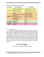
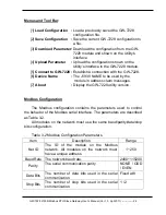
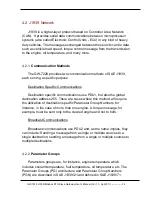
2.8 Cable Selection
The CAN bus is a balanced (differential) 2-wire interface running over
either a Shielded Twisted Pair (STP), Un-shielded Twisted Pair (UTP), or
Ribbon cable. The CAN-L and CAN-H Wire start on one end of the total
CAN network that a terminator of 120 Ohm is connected between CAN-L
and CAN-H. The cable is connected from CAN node to CAN node,
normally without or with short T connections. On the other end of the cable
again a 120
Ω
(Ohm) terminator resistor is connected between the CAN
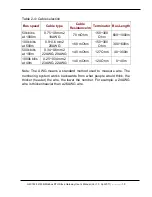
lines. How to decide a cable type, cable length, and terminator depends
on the baud rate in the CAN bus network, please refer to the following
table 2-4.
Figure 2-18
:
Un-shielded Twisted Pair (UTP)