background image


GW-5492/GW-5493  User’s Manual  

V1.01  2011/09/01 


16 


Figure 10. Devices addition and RTU configuration 

Modbus RTU configuration as shown in Figure 10 


ID: Any valid string and number to represent a Modbus Device 


COM Port: COM2 or COM3 


DeviceID:  This number is often referred  to  unit number  or slave ID. The number must be 

equal to the remote slave device setting. 

Modbus TCP configuration as shown in Figure 11 


Figure 11. TCP configuration 


ID: Any valid string and number to represent a Modbus Device 


TCP Address: Remote slave Device IP address 


Port: Remote slave Device Port number. The default port number is 502. 


Unit: This number is often referred to unit number or slave ID 

Summary of Contents for GW-5492

Page 1: ...GW 5492 GW 5493 User s Manual v1 0 ICP DAS BACnet to Modbus Gateway ...

Page 2: ...nge this manual at any time without notice The information furnished by ICP DAS is believed to be accurate and reliable However no responsibility is assumed by ICP DAS for its use or for any infringements of patents or other rights of third parties resulting from its use Copyright All rights are reserved by ICP DAS Co Ltd 2012 Trademark The names used for identification only may be registered trad...

Page 3: ...lection 8 3 3 Using Web based Configuration Tool 8 3 4 Tab menu of Configuration Tool 11 3 4 1 System 11 3 4 2 Modbus 11 3 4 3 BACnet 11 3 4 4 Modbus BACnet Mapping 11 3 5 System tab 12 3 5 1 System Process 13 3 5 2 Network Settings 13 3 5 3 Serial Port Settings 13 3 5 4 Import Export Updating Firmware 14 3 5 5 Change User Name Passsword 14 3 6 Modbus tab 15 3 6 1 Devices addition 15 3 6 2 Devices...

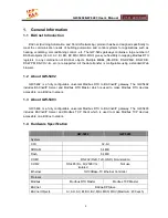
Page 4: ...able using a standard Web browser 1 2 About GW 5492 GW 5492 is a fully configurable universal Modbus RTU to BACnet IP gateway The GW 5492 includes BACnet IP Server and Modbus RTU Master which is used to make Modbus RTU devices accessible on a BACnet network 1 3 About GW 5493 GW 5493 is a fully configurable universal Modbus RTU to BACnet IP gateway The GW 5493 includes BACnet IP Server and Modbus T...

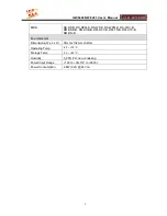
Page 5: ...P B DS WPM B DS COV B DM DDB B DM DOB B DM DCC B DM TS B DM UTC B DM RD B Environmental Dimensions W x L x H 91mm x132mm x 52mm Operating Temp 25 75 C Storage Temp 30 85 C Humidity 5_90 PH non condesing Power Input Range 10V to 30 10V to 30VDC Power Consumption 4 8W 0 2A 24VDC ...

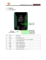
Page 6: ...Description 1 F G Firm Ground 2 GND Ground of power supply 3 VS V of power supply 10V to 30VDC unregulated 4 TxD TxD of COM3 RS 232 5 RxD RxD of COM3 RS 232 6 Data Data of COM2 RS 485 7 Data Data of COM2 RS 485 8 GND Ground of COM1 RS 232 9 TxD TxD of COM1 RS 232 10 RxD RxD of COM1 RS 232 ...

Page 7: ...eeds 10 30 VDC power input and consumes 4 8W The Power LED will be turn on after applying power and it will be flashing two times per second 2 2 2 Module Status indicator LED The LED indicates the communication status of the GW 5492 GW 5493 The following description shoes the conditions of error status Green light flashes BACnet Client is communicating with GW 5492 GW 5493 Red light flashes Time o...

Page 8: ...cture software operating interfaces and configuration of BACnet and Modbus mapping GW 5492 GW 5493 provides Web based configuration for the BACnet and Modbus settings The functions include System information and configuration Network and COM Port settings Management and settings of Device s Points Address for Modbus RTU Master and TCP Client BACnet configuration and management BACnet Instance and ...

Page 9: ... 192 168 0 254 For security reason user will have to login with user name and password before entering the configuration pages The default user name and password are admin and admin Figure 1 Logon screen Screen opened as image shown in Figure 2 if success login Select a hardware to enter a correspond page ...

Page 10: ...GW 5492 GW 5493 User s Manual V1 01 2011 09 01 10 Figure 2 Gateway selection page ...

Page 11: ...ts settings only for GW 5492 Firmware Updating User name and password configuration 3 4 2 Modbus Modbus Master Configuration consists of Add or delete slave devices Modbus protocol mode settings RTU mode for GW 5492 and TCP Mode for GW 5493 Add or delete device points Point settings including slave device s address data type and so on 3 4 3 BACnet BACnet Server Configuration consists of BACnet IP ...

Page 12: ...Daemon running status and operate its state start or stop 2 Network Settings LANs are provided for either BACnet IP or Modbus TCP protocol 3 Serial Port Settings The configuration consists of two serial ports COM1 RS 485 and COM2 RS 232 settings Two serial ports are provided for Modbus RTU protocol 4 Import Export Updating Firmware Import or export of configuration file and updating firmware 5 Cha...

Page 13: ...king Figure 4 System Process 3 5 2 Network Settings Network Settings consists an Ethernet LAN settings provided for either BACnet IP or Modbus TCP protocol All information isn t saved until clicking the Save Settings button Figure 5 Network Settings 3 5 3 Serial Port Settings The configuration consists of two serial ports COM2 RS 485 and COM3 RS 232 settings Two serial ports are provided for Modbu...

Page 14: ... a specific format of the cvs file by choosing the file path and importing the file by clicking Config Import button The current firmware version is showed The firmware can also be updated from a fw file downloaded from ICP DAS by choosing the file path and click Upload Firmware to upload file to device After fw file uploaded click Update Firmware button to update firmware After firmware updated p...

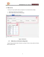
Page 15: ...ces list 3 Modbus RTU GW 5492 or Modbus TCP GW 5493 settings 4 Point ID and address settings 5 Operation buttons Figure 9 Modbus tab 3 6 1 Devices addition a Click Devices as shown in Figure 10 b The protocol type has already defined when selecting hardware RTU for GW 5492 and TCP for GW 5493 Please refer to Figure 10 and 11 c Click Save button to add and save a new Modbus device ...

Page 16: ...viceID This number is often referred to unit number or slave ID The number must be equal to the remote slave device setting Modbus TCP configuration as shown in Figure 11 Figure 11 TCP configuration ID Any valid string and number to represent a Modbus Device TCP Address Remote slave Device IP address Port Remote slave Device Port number The default port number is 502 Unit This number is often refe...
Page 17: ...shown in Figure 12 the string with the shadow b The sub frame on the right shows selected Device information Figure 12 Device and point information Point management a As shown in Figure 13 input a point name and click Add button to add a new point b Fill this point information the detail description as follows ...

Page 18: ... including BIT CHAR UCHAR INT16 UINT16 INT32 UINT32 FLOAT and DOUBLE Sampling Polling period for this point The minimum unit is ms TimeOut Time out for waiting ScaleFactor and Intercept Scaling applies the formula y mx b When reading from the slave the raw data as read is multiplied by the scale factor and then the offset is added to produce the resulting Present Value Present Value raw data value...

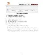
Page 19: ...on The detail description as follows 1 BACnet basic information and configuration 2 BACnet Object Types and max instance settings Figure 14 BACnet tab 3 7 1 BACnet basic information configuration Figure 13 shows the BACnet basic information consisting of Protocol Communication and Device Object properties settings ...

Page 20: ..._Offset The time offset from Coordinated Universal Time Location Location property Description Object_ Description property 3 7 2 BACnet Object Types and instance settings The BACnet Gateway supports 10 types of standard BACnet Objects including Analog Input Analog Output Analog Value Binary Input Binary Output Binary Value Multistate Input Multistate Output Multistate Value and Device Figure 15 s...

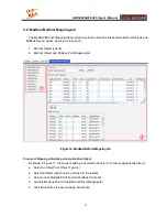
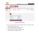
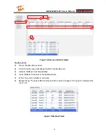
Page 21: ...dbus Point Mapping list Figure 16 Modbus BACnet Mapping tab Process of Mapping a Modbus point to a BACnet Object As shown in Figure 17 the steps of adding a new BACnet Object into the mapping list as follows a Select an Object from Object Type list b Selected Object type should be showed in the textbox c Select one of Modbus Point from the Modbus Points list d Add this Modbus Point to the BACnet O...

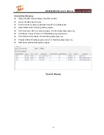
Page 22: ...steps of removing a new BACnet Object from mapping list as follows a Select an Object from Object Type list b Selected Object type should be showed in the textbox c Select one of BACnet Object in the Mapping list d Remove this Object from the BACnet Object Mapping list e Click Save button to save mapping information ...

Page 23: ...Device name Point Point ID same as Modbus Point ID in the Modbus tab Address Modbus Point initial address Index Modbus Point index of the address blocks Write The point is writable or read only Mapped Type The type of BACnet objects that the point is mapped If the point isn t mapped the row is null Figure 19 Modbus Points ...

Page 24: ...Point ID in the Modbus tab Object Name BACnet Object_Name property COV Increment COV_Increment property For the Analog object type only COVPeriod The period time of COVNotification required service Unit BACnet Unit property For the Analog object type only Polarity BACnet Polarity property mode For the Binary object type only Description BACnet Description property Figure 20 Mapping ...

Reviews: