ICP DAS USA ET-8KP4-MTCP Quick Start Manual Download Page 2

Copyright ©  2016 ICP DAS Co., Ltd. All Rights Reserved. 

2


P. 2 

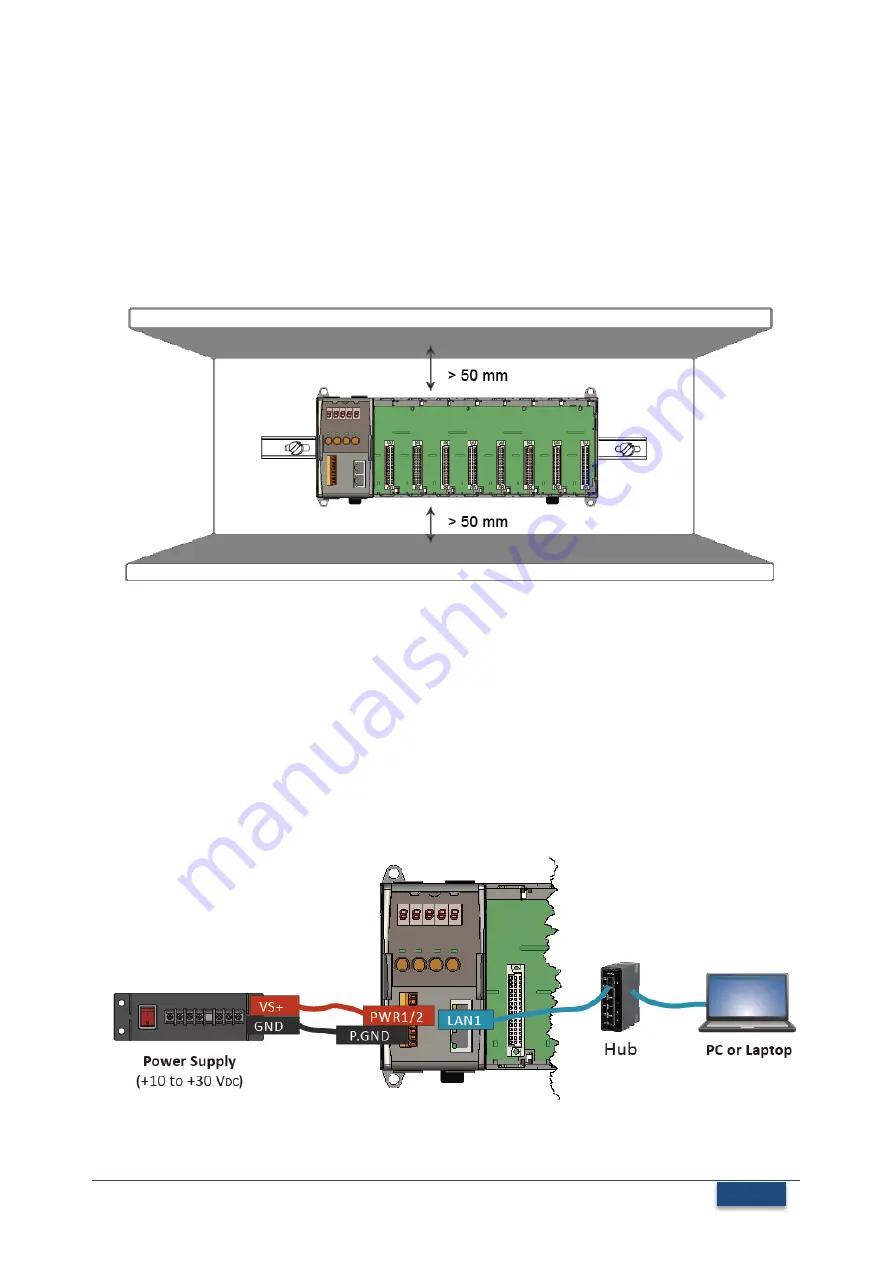
Mounting the Hardware


The ET-8KPn-MTCP installation must provide proper ventilation, spacing, and grounding 

to ensure the equipment will operate as specified. A minimum clearance of 50mm 

between the ET-8KPn-MTCP and the top and bottom side of the enclosure panels must 

be provided. 


Connecting to PC, Network and Setting up the Power


i. Connect 

PC 

to 

LAN1 

port through a 

hub

. The ET-8KPn-MTCP is equipped with RJ-45 

Ethernet ports for connection to an Ethernet hub/switch and PC. You can also link 

directly the ET-8KPn to PC with an Ethernet cable 

ii. Connect the 

+24 V

DC 

power supply 

to 

PWR1/PWR2 

and 

GND 

terminals 


Summary of Contents for ET-8KP4-MTCP

Page 1: ...provide information needed to get started Please also consult the User Manual for detailed information on the setup and use of ET 8KPn MTCP In addition to this guide the package includes the following...

Page 2: ...e of 50mm between the ET 8KPn MTCP and the top and bottom side of the enclosure panels must be provided 2 Connecting to PC Network and Setting up the Power i Connect PC to LAN1 port through a hub The...

Page 3: ...ration process ensure that the LAN1 are used to connect to network and make the controller under the running firmware mode The default IP addresses are as follows Item LAN1 default IP Address 192 168...

Page 4: ...settings iv Click the OK button to save the configuration 5 Inserting and Wiring the I O Modules There are various types of I O expansion modules for interfacing many different field devices to the E...

Page 5: ...en the ET 8KPn MTCP and PC Laptop via the Modbus TCP protocol Step 1 Run the Modbus Utility and connect to ET 8KPn MTCP i Double click the Modbus Utility shortcut on the desktop ii Click the Modbus TC...

Page 6: ...O modules to configuration of the controller ii Select the About option from the Help menu to get the I O configuration and firmware information iii Check the module status diagram ensuring for the I...

Page 7: ...uration get the I O values and then save the I O configuration i Configure the I O settings such as Range Code Power on and Safe values ii Select the Timer Interval from the Monitor menu to set the mo...

Page 8: ...g tables iv Select File option from the Save menu and select a location where the configuration file is about to be saved This operation can save the controller configuration and I O settings to an in...

Reviews: