background image


24 

PDX3-090T      DM&P Vortex86DX3 Panel PC with 9” WSVGA TFT LCD 

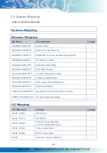
0061h   

Port B + NMI Control Port 

0062h - 0063h   

8051 download 4K Address Counter 

0064h   

Keyboard / Mouse Status / Command Port 

0065h   

WatchDog0 Reload Counter 

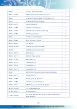
0070h - 0071h   

CMOS RAM Port 

0072h - 0075h 

MTBF Control Register 

0078h - 007Ch 

GPIO Port 0,1,2,3,4 Default Setup 

0080h - 008Fh   

DMA Page Register 

0092h   

System Control Register 

0098h - 009Ch   

GPIO Direction Control 

00A0h - 00A1h   

PIC 8259-2 

00A8h - 00ADh   

WatchDog1 Control Register 

00AEh   

WatchDog1 Reload Counter 

00C0h - 00DFh 

DMA 8237-2 

00E0h - 00EFh   

DOS 4G Page Access 

0170h - 0177h   

IDE1 (IRQ 15) 

02E8h - 02EFh   

COM4 (IRQ 11) 


02F8h - 02FFh   

COM2 (IRQ 3) 


03E8h - 03EFh   

COM3 (IRQ 10) 


03F6h 

IDE1 ATAPI Device Control Write only Register 

03F8h - 03FFh 

COM1 (IRQ 4) 

0480h - 048Fh   

DMA High Page Register 

0490h - 0499h   

Instruction Counter Register 

04D0h - 04D1h   

8259 Edge,/ Level Control Register 

0CF8h - 0CFFh   

PCI configuration port 

EF00h - EFFFh   

On Board LAN   

FC00h - FC05h   

SPI Flash BIOS Control Register (internal SPI Flash 
Base address) 

Summary of Contents for PDX2-090T-P5A

Page 1: ...i DM P Vortex86DX3 Panel PC with 9 TFT LCD Model PDX3 090T 5A PDX3 090T 8A PDX3 090T 5A 2G PDX3 090T 8A 2G PDX2 090T P5A PDX2 090T P8A PDX2 090T P5A 2G PDX2 090T P8A 2G User s Manual Revision 1 3A...

Page 2: ...n Description 2016 11 18 Version 1 0 Initial Release 2017 01 10 Version 1 1 Specification correction 2019 07 30 Version 1 2 Add Section 1 3 Note 5 instruction 2021 08 31 Version 1 3 Add Projected Capa...

Page 3: ...ctive owners All names mentioned herewith are served for identification purpose only Safety Information Read these Safety instructions carefully Make sure the voltage of the power source is correct be...

Page 4: ...1 4 Product Dimension 10 1 5 Panel Mounting Instruction 11 1 6 Ordering Information 13 1 7 Packing List 15 2 System Installation 16 2 1 CPU Board Outline 16 2 2 Connector Summary 17 2 3 Connector Pin...

Page 5: ...nly minimum power requirement when running at 1GHz and DDR3 memory provides faster data transfer rate By using 9 TFT LCD PDX3 090T becomes the perfect choice for a limited budget In additional the int...

Page 6: ...programmable from 30 5u to 512 seconds x 2 sets LAN Integrated 10 100M Ethernet Audio HD Audio Realtek ALC262 CODEC Internal Drives Compact Flash Type I II slot Micro SD slot Optional 1GB or 2GB Flas...

Page 7: ...CD Specifications Display Type 9 TFT LCD Backlight Unit LED Display Resolution 1024 W x 600 H Brightness cd m2 300 nits Contrast Ratio 500 1 Display Color 262 144 Pixel Pitch mm 190 5 H x 189 V Viewin...

Page 8: ...0T DM P Vortex86DX3 Panel PC with 9 WSVGA TFT LCD Type2 Projected Capacitive Touch Screen Optional Resolution 25ppi Min Transparency 86 2 Accuracy Within 2 5mm each target Surface Hardness 7H Pressure...

Page 9: ...OK if mura is slight visible through 6 ND filter ELECTRICAL DEFECT BRIGHT DOT A Grade B Grade C Area O Area Total C Area O Area Total Note3 N 0 N 2 N 2 N 2 N 3 N 5 Note2 DARK DOT N 2 N 3 N 3 N 3 N 5 N...

Page 10: ...X3 Panel PC with 9 WSVGA TFT LCD Note 1 W Width mm L Length mm N Number Average Diameter 1 White Black Spot 2 Polarizer Bubble Fig 1 1 Fig 1 2 Note 2 Bright dot is defined through 6 transmission ND Fi...

Page 11: ...efect dots including bright and dart adjacent dot And they will be counted 2 defect dots in total quantity R R G G R G R R G G R G R R G G R G R R G G R G R R G G R G R R G G R G R R Defect Dot Adjace...

Page 12: ...LCD display is turned off for a period of time but some image retention may be not reversible when LCD encounters screen burn The following is LCD manufacturer s test result for customers reference T...

Page 13: ...9 PDX3 090T DM P Vortex86DX3 Panel PC with 9 WSVGA TFT LCD 3 After 5 mins the mura must be disappeared completely...

Page 14: ...10 PDX3 090T DM P Vortex86DX3 Panel PC with 9 WSVGA TFT LCD 1 4 Product Dimension Fig 1 4 Product Dimension...

Page 15: ...T face down on a clean flat surface 4 Slide the panel cutout around the back of PDX3 090T until the panel rests directly on the gasket Make sure the screw holes align with the screw holes on PDX3 090T...

Page 16: ...machine shop cut the mounting hole in the panel Note 2 The length for all twelve M3 screws will be according to the thickness of mounting panel For example The length of standard M3 screws for PDX3 09...

Page 17: ...nel PC w 2GB DDR3 2USB Line Out LAN COM CF or MicroSD RTP Power Adapter PDX3 090T 8A 2G 9 Panel PC w 2GB DDR3 2USB Line Out LAN COM CF or MicroSD RTP 8 35 DC Support PDX3 090T P5A 9 Panel PC w 1GB DDR...

Page 18: ...D RTP Power Adapter PDX3 090T 8A 2G I 9 Panel PC w 2GB DDR3 Wide Temp 2USB Line Out LAN COM CF or MicroSD RTP 8 35 DC Support PDX3 090T P5A I 9 Panel PC w 1GB DDR3 Wide Temp 2USB Line Out LAN COM CF o...

Page 19: ...0T P8A PDX3 090T P5A 2G PDX3 090T P5A 2G Power 20W 3PIN PDX3 090T P8A 2G PDX3 090T P8A 2G PDX3 090T 5A I PDX3 090T 5A I Power 20W 3PIN PDX3 090T 8A I PDX3 090T 8A I PDX3 090T 5A 2G I PDX3 090T 5A 2G I...

Page 20: ...16 PDX3 090T DM P Vortex86DX3 Panel PC with 9 WSVGA TFT LCD 2 System Installation 2 1 CPU Board Outline Fig 2 1 PDX3 CPU Board...

Page 21: ...r 9 pin J14 VGA 2 0mm 10 pin box header 10 pin J18 Micro SD Card Socket Optional Micro SD socket J23 Audio Line Out 1 25mm Phone Jack J24 Audio Mic In 2 0mm 4 pin wafer 4 pin J25 COM3 TX RX 1 25mm 3 p...

Page 22: ...J5 USB Optional Pin Signal Name 1 VCC 2 USBD1 3 USBD1 4 GND 5 GND J8 PS 2 Keyboard Pin Signal Name Pin Signal Name 1 KBCLK 2 KBDAT 3 NC 4 GND 5 VCC J9 PS 2 Keyboard Pin Signal Name Pin Signal Name 1...

Page 23: ...MICVREF 2 GND 3 GND 4 MIC IN J25 COM3 TX RX Pin Signal Name 1 GND 2 TXD3 3 RXD3 J26 COM4 TX RX Pin Signal Name 1 GND 2 TXD4 3 RXD4 J31 4 Wires Touch connector Pin Signal Name 1 Y 2 X 3 Y 4 X J32 USB...

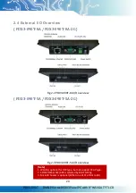
Page 24: ...090T 8A PDX3 090T 8A 2G Fig 2 2 PDX3 090T 8A I O overview PDX3 090T 5A PDX3 090T 5A 2G Fig 2 3 PDX3 090T 5A I O overview Note 1 WLAN is optional for RTP type but not support PCAP type 2 COM1 RS232 422...

Page 25: ...F Power Connector 5A Pin Signal Name 1 5V 2 GND 3 NC Power Connector 8A Pin Signal Name 1 8 35V 2 GND Audio Line Out Pin Signal Name 1 GND 2 LOUTL 3 Open Touch 4 Open Touch 5 VREFOUT USB Port Pin Sign...

Page 26: ...10 COM1 RS232 422 485 Change setting by BIOS Pin Signal Name Pin Signal Name 1 DCD1 422TX RS485 2 RXD1 422TX RS485 3 TXD1 422RX 4 DTR1 422RX 5 GND 6 DSR1 7 RTS1 8 CTS1 9 RI1 RJ45 Pin Signal Name Pin S...

Page 27: ...VGA BIOS ROM 000C8000 000CFFFF Boot ROM Enable 000CC000 000CFFFF Console Redirection Enable 000D0000 000DFFFF Expansion ROM Space 000E0000 000EFFFF USB Legacy SCSI ROM Space 000F0000 000FFFFF Motherb...

Page 28: ...irection Control 00A0h 00A1h PIC 8259 2 00A8h 00ADh WatchDog1 Control Register 00AEh WatchDog1 Reload Counter 00C0h 00DFh DMA 8237 2 00E0h 00EFh DOS 4G Page Access 0170h 0177h IDE1 IRQ 15 02E8h 02EFh...

Page 29: ...de for IRQ8 15 IRQ3 Unassigned IRQ4 Serial Port 1 IRQ5 VGA IRQ6 Audio IRQ7 Ethernet 10 100M LAN IRQ8 Real Time Clock IRQ9 Unassigned IRQ10 USB IRQ11 USB IRQ12 Mouse IRQ13 Math Coprocessor IRQ14 Hard D...

Page 30: ...9 WSVGA TFT LCD 2 7 Watchdog Timer There are two watchdog timers in PDX3 090T we also provide DOS Linux and WinCE example for your reference For more technical support please visit http tech icop com...

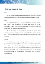
Page 31: ...and IRQ settings can be done by software with the supplied utility software or it can be set for Plug and Play compatibility The controller supports Half Full Duplex Ethernet function to double channe...

Page 32: ...ail information please visit DMP official website dmp com tw tech 3 1 PDX3 090T Development Note Primary IDE Master or Slave 1 Primary IDE Device can be either one of CF or Micro SD and the standard v...

Page 33: ...e forced the IDE setting in BIOS to PIO mode before install Linux on PDX3 090T as follows Go to the advanced BIOS setting and make the Onboard IDE Operate Mode is Legacy Mode Windows XP and Windows 7...

Page 34: ...system cannot be booted after BIOS changes are made Please follow below procedures in order to restore the CMOS as default setting Press End Key when the power on Press Del to enter the AMI BIOS setup...

Page 35: ...ny damages lost profits lost savings or any other incidental or consequential damage resulting from the use misuse of originality to use this product Vendor will not be liable for any claim made by an...

Reviews: