1-1-32 Kamiminami, Hirano-ku, Osaka 547-0003, Japan
A-6838W-6US
Printed in Japan
© 2011 Icom Inc.
MODE
DC
LAN
TRX1
TRX2
TRX3
IN
+
+
+
OUT
SW
ABC
GROUND
w
e
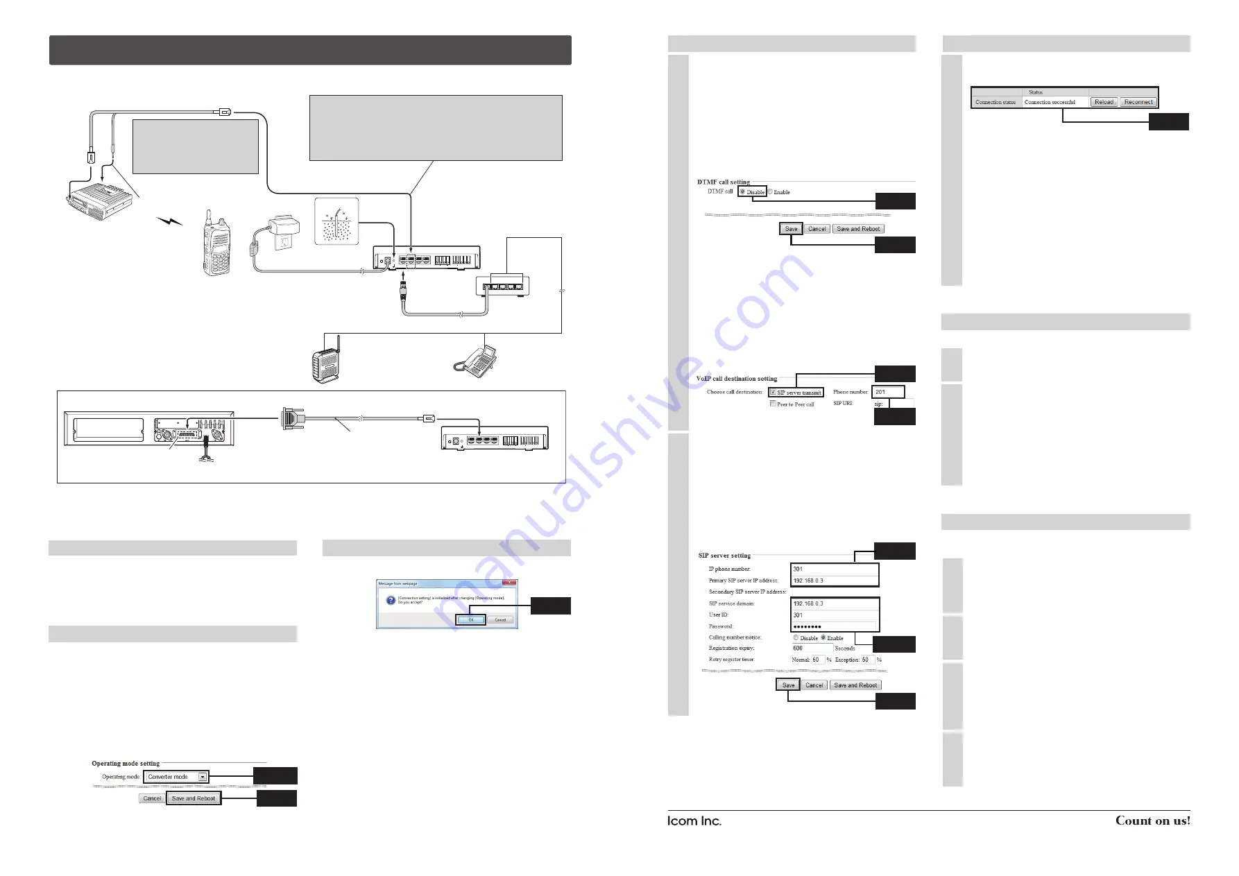
To the [TRX1] port
HUB
Connect to LAN
Connect to
unused ports
(192.168.0.2)
[TRX1] extension number : 301
User ID
: 301
Password
: 14ak96wd
VE-PG2
Transceiver A
channel 1
Operator A
Transceiver B
channel 1
Connect the transceiver’s microphone connector and speaker plug.
Figure 4: Converter mode setting example
NOTE: First, connect the transceiver
to the VE-PG2 using the specified
connection cable. Then turn ON the
power to the transceiver and the
VE-PG2.
Turn the transceivers’ power ON,
and then set transceiver A’s
volume to the 12 o’clock position.
Connect to the transceiver’s speaker jack.
CAUTION:
To connect the transceivers or repeaters, use only the following cables:
OPC-2073 (For the transceivers) and OPC-2074. (For the repeaters)
Connect only the specified cables to [TRX1], [TRX2] or [TRX3].
Using another cable, like an Ethernet cable, or connecting the cables to
[LAN] may damage the VE-PG2, transceivers or repeaters.
NOTE: When using a repeater, connect the optional OPC-2074 to the repeater’s ACC connector.
Repeater’s rear panel
OPC-2074
ACC connector
MODE
DC
LAN
TRX1
TRX2
TRX3
IN
+
+
+
OUT
SW
ABC
Connect the specified cables to
[TRX1], [TRX2] or [TRX3] only.
Set External I/O (D-sub 25) port setting* to Ext. I/O 18 Output Low Voltage 2.
*The CS-FR5000 cloning software and OPC-1122U cloning cable are required when you set External I/O D-sub 25 port setting.
q
1
2
3
4
5
Connect the LAN cable between
the VE-PG2 and the HUB.
LAN cable (straight type: the 3rd party products)
To the [LAN] port
IP router
192.168.0.3
Operator B
IP telephone
extension number: 201
This explanation describes how you set the VE-PG2 to the Converter mode using the detail configuration wizard and
connection, shown below.
‘
Set the VE-PG2 to the Converter mode using the detail configuration wizard
If you want to operate the VE-PG2 in the “Peer to Peer call mode,” download the VE-PG2 instruction manual from Icom web
site http://www.icom.co.jp/world/, and see the instruction manual for details.
1. Set the IP router’s telephone book
Set the extension numbers, and other settings of the IP
telephone and the VE-PG2’s [TRX1] port (to connect the
transceiver) into the IP router’s telephone book, as follows.
• IP telephone
: 201
• VE-PG2’s [TRX1] port : 301
2. “Operating mode setting” setting
q
Select
w
Click
• Save the VE-PG2 setting to the setting file, if necessary.
Refer to the VE-PG2 instruction manual (PDF file:
Download from the Icom web site) for details.
q
After making the connections as shown in Figure 4, turn
ON transceiver A’s power, then open the setting screen
with your browser (see the Installation guide
q
).
w
Click the “Operating mode setting” in the “Connection
setting,” and then select “Converter mode.”
e
Click the [Save and Reboot] button.
r
Click [OK] when the dialog box below appears.
t
Click [Back] on the screen after the reboot finishes
(about 30 seconds later).
• “Connection setting” will be return all settings to their default
values when the “Operating mode” setting is modified.
2. “Operating mode setting” setting (continued)
q
Set “IP router setting” as shown Figure 4.
(Example) • Enter “301” into “IP phone number.”
• Enter “192.168.0.3” into “Primary IP
router IP address.”
• Enter “192.168.0.3” into “IP router
domain.”
• Enter “301” into “User ID.”
• Enter “14ak96wd” into “Password.”
w
Click [Save].
2
3. VE-PG2’s [TRX1] port setting
NOTE:
If you want to set “VoIP call destination
setting,” first:
• Move the mouse pointer to “Connection
setting,” “TRX/EXT.”
• Select either “Transceiver 1 (TRX1),”
“Transceiver 2 (TRX2)” or “Transceiver 3
(TRX3).”
• Set “DTMF call” to “Disable” in the “DTMF
call setting.”
• Click [Save].
q
M ove t h e m o u s e p o i n t e r t o “ C o n n e c t i o n
setting,” “IP network connection,” and then click
“Transceiver 1 (TRX1).”
w
Set “VoIP call destination setting” for the IP router
transmit as shown Figure 4.
(Example) • Click the “SIP server transmit” check
box.
• Enter “201” into “Phone number.”
1
e
Click
r
Enter
e
Click
q
Enter
w
Enter
5. How to communicate
1
2
This setting example refers to the connections in Figure 4.
Follow the steps for the IP telephone calling transceiver B.
Operator A holds down transceiver B’s [PTT], and
speaks into the microphone at their normal voice
level to call the IP telephone.
Then they release transceiver B’s [PTT] to receive.
The IP telephone rings, operator B takes the IP
telephone handset off the hook, and speaks into the
telephone at their normal voice level.
4. Transceiver setting
Turn ON transceiver B’s power, and select the same
operating channel as transceiver A.
• Set the same channel on all the transceivers, to
communicate with transceiver A.
See the transceiver’s instruction manual when
setting the channel, if necessary.
(Example) In the illustration Figure 4, set transceivers
A and B to channel 1.
2
This setting example refers to the connections in Figure 4.
When operator B is finished speaking on the IP
telephone, operator A holds down transceiver B’s
[PTT], and speaks into the microphone at their
normal voice level.
Then they release transceiver B’s [PTT] to receive.
The VE-PG2 disconnects when no audio received
from transceiver B or the IP telephone for 15
seconds.
Or put the IP telephone handset on the hook.
4
Set transceiver A’s AF volume to the 12 o’clock
position.
1
q
Click
3
Confirm “Connection successful” is displayed in the
“Status” of the “Connection status,” as shown below.
NOTE:
• Click [Reload] if you want to confirm the VE-PG2’s
latest connection status.
• “Connection status” has 3 buttons:
[Reload]
: Click this button to display the
VE-PG2’s latest connection status.
[Reconnect] : Click this button to reconnect
the VE-PG2 and the transceiver
connected to [TRX1]–[TRX3].
[Disconnect] : Click this button to disconnect
the VE-PG2 and the transceiver
connected to [TRX1]–[TRX3].
3
Confirm
3. VE-PG2’s [TRX1] port setting (Continued)
w
Click
e
Click


