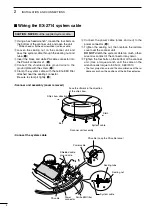
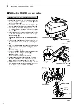
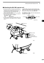
background image

5

2

INSTALLATION AND CONNECTIONS

1
2
3
4
5
6
7
8
9
10
11
12
13
14
15
16
17
18
19
20
21

D


Location

R

 WARNING! BE SURE the radar’s power is OFF* 

whenever you are working with the scanner unit.

* The radar’s power automatically turns OFF approx. 30 sec. 

after the display unit’s power is turned OFF.

   When  2  display  units  are  connected  to  the 

MarineCommander™, all units’ power must be turned OFF.

The scanner unit is designed for high-pressure water 
jet resistance (except for the cable connectors). Select 
a place for installation which meets the following im-
portant conditions.

q

  The scanner unit must be near the boat’s center line 

and have a good view in every direction. Be sure 
there are no objects in the surrounding area which 
will intercept the scanning beam.

w

  Keep the scanner unit away from any smoke-stacks. 

Smoke can damage the unit. 

e

  When the boat is equipped with a Radio Directional 

Finder (RDF) system, keep the scanner unit at least 
2 m (6.6 ft) away from any RDF antenna. 

  •  Radiation from the scanner unit can affect the measure-

ment data of RDF equipment. 

r

  The unit should be placed as high as possible on 

the boat to obtain best performance with maximum 
range.

t

  If you install two or more radar in one boat, install  

one above, and one below.

y

  The  mounting  surface  must  be  parallel  with  the 

boat’s waterline.

u

  If the height is insufficient to install the scanner unit, 

build a special frame for installation.

D


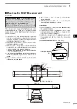
Mounting

q

  Drill four holes of 12 mm (0.47 in) in diameter using 

the supplied template.

w

  If the mounting surface or platform is metal, apply 

sealing compound around the holes to prevent cor-
rosion and to waterproof the unit. 

e

  Attach the scanner unit to the selected position with 

the  supplied  bolts  (M10

×

40  mm),  flat  and  spring 

washers.

CAUTION: SECURE the four bolts firmly.

Ship’s bow direction

190 (7.48)

399 (15.71)

381 (15)

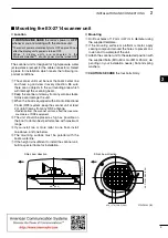
 Mounting the EX-2780 scanner unit

Ship’s bow direction

302 (11.89)

248 (9.76)

1200 (47.24)

20.5 (0.81)

R5.5 (0.22)

11 (0.43)

262 (10.31)

281 (11.06)

98 (3.86)

152 (5.98)

190 (7.48)

Unit: mm (in)

Summary of Contents for MXR-5000R

Page 1: ...N MANUAL MARINE RADAR MXR 5000R Radome type MXR 5000T Open array type This device complies with Part 15 of the FCC Rules Op eration is subject to the condition that this device does not cause harmful interference ...

Page 2: ...unit 1 set EX 2714 Radome type for MXR 5000R System cable OPC 1188A 15 m 1 Bolts M10 50 mm 4 Bolts M10 25 mm 4 Nuts M10 4 Flat washers M10 4 Spring washers M10 4 EX 2780 Open array type for MXR 5000T System cable OPC 1189A 20 m 1 Bolts M10 40 mm 4 Nuts M10 4 Flat washers M10 4 Spring washers M10 4 Allen wrench 1 Cap bolts M8 18 mm 4 Belleville washers M8 4 Sealing washers T 4 Flat washers M8 4 Gro...

Page 3: ...f seals For Scanner unit R DANGER HIGH VOLTAGE NEVER open the scanner unit The scanner unit contains high volt age that could be fatal And there are no user adjust ment points All repairs and adjustments MUST be made by a qualified electronics technician at your Marine Navigation Dealer For qualified electronics technician only R DANGER HIGH VOLTAGE High volt ages of up to 3 500 volts are used in ...

Page 4: ... 2 meters and is appropriate for all vessels For watercraft without suitable structures the antenna must be mounted so as to maintain a minimum of 1 meter vertically between the antenna measured from the lowest point of the antenna to the heads of all persons AND all persons must stay outside of the 3 5 meter MPE radius Do not transmit with radar and antenna when persons are within the MPE radius ...

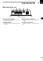
Page 5: ... supply through the supplied DC power cable wGROUND TERMINALS Connect these terminals to ground to prevent elec trical shocks eMarineCommander CONNECTOR Connect this connector to the Icom MarineCom mander rSCANNER UNIT CONNECTOR Connect this connector to the supplied scanner unit q w r e This terminal is not used MXR 5000 Radar unit ...

Page 6: ...ty is correct Red Positive terminal Black Negative _ terminal Fuse rating of the DC power cable is correct The 10 A fuse is pre installed 5 A For 24 V power source 10 A For 12 V power source Ground connection To prevent electrical shocks and other problems ground the radar unit through the GND terminal For best results connect a heavy gauge wire or strap to the nearest grounding point on the boat ...

Page 7: ...inder RDF system keep the scanner unit at least 2 m 6 6 ft away from any RDF antenna Radiation from the scanner unit can affect the measure ment data of RDF equipment r The unit should be placed as high as possible on the boat to obtain best performance with maximum range t If you install two or more radar in one boat install one above and one below y The mounting surface must be parallel with the...

Page 8: ... black and red to the power connector t u Tighten the sealing nut then replace the radome cover over the scanner unit DO NOT stretch the system cable too much other wise miss contact of the connector may occur i Tighten the four bolts on the bottom of the scanner unit Use a torque wrench until the scale on the wrench reads torque to 5 0 N m 3 69 lbf ft The four projections around the circumference...

Page 9: ...ystem keep the scanner unit at least 2 m 6 6 ft away from any RDF antenna Radiation from the scanner unit can affect the measure ment data of RDF equipment r The unit should be placed as high as possible on the boat to obtain best performance with maximum range t If you install two or more radar in one boat install one above and one below y The mounting surface must be parallel with the boat s wat...

Page 10: ...lamp the system cable with the cable clamp metal fitting using a screw near the sealing connector i Be sure to clamp it tightly u Clamp the system cable with the ferrite EMI filter attached near the sealing connector o Be sure to clamp it tightly Secure the ferrite EMI filter with cable tie i Tighten the sealing nut then close the top cover DO NOT stretch the system cable too much other wise miss ...

Page 11: ...facture ESSO Type BEACON 325 e Connect the grounding wire purchase locally to the ground plate with the supplied terminal if required Fig 2 NOTE When using the optional system cable Peel the outer sheath of the system cable when using the optional system cable OPC 1078 BE CAREFUL DO NOT cut the inner shield wire when peeling the outer sheath Unit mm in Peel the sheath To the display To the scanner...

Page 12: ...roperly rated one as shown at right Options OPC 1895 connection cable Allows you to connect the Icom MarineCommander system 20 m 65 6 ft OPC 1077 system cable Allows you to install the radar unit and scanner unit up to 20 m 65 6 ft apart For MXR 5000R only OPC 1078 system cable Allows you to install the radar unit and scanner unit up to 30 m 98 4 ft apart Fuse rating 10 A for 12 V power source 5 A...

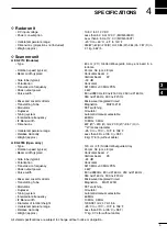
Page 13: ...ual selectable Intermediate frequency 60 MHz IF Band width 10 MHz 3 MHz Dimensions 607 Ø 243 H mm 23 9 Ø 9 57 H in Ø means diameter Usable temperature range 25 C to 70 C 13 F to 158 F Relative Humidity Less than 95 at 35 C 95 F Weight approx 8 kg 17 5 lb without cable EX 2780 Open array Type 120 cm 4 ft Slotted Waveguide Array Rotation speed typical 24 rpm 36 rpm 48 rpm Beam width typical Horizont...

Page 14: ...MEMO ...

Page 15: ...MEMO ...

Page 16: ...1 1 32 Kamiminami Hirano ku Osaka 547 0003 Japan A 6752H 1EX w Printed in Japan 2009 2011 Icom Inc ...

Reviews: