INSTRUCTION MANUAL
iM31
VHF MARINE TRANSCEIVER
New2001
IC-M31.qxd 03.10.20 9:18 AM Page 1 (1,1)
Page 1: ......
Page 2: ...ON CLEAN THE TRANSCEIVER THOROUGHLY WITH FRESH WATER after exposure to saltwater and dry it before opera tion Otherwise the transceiver s keys switches and con trollers may become inoperable due to salt crystallization ...
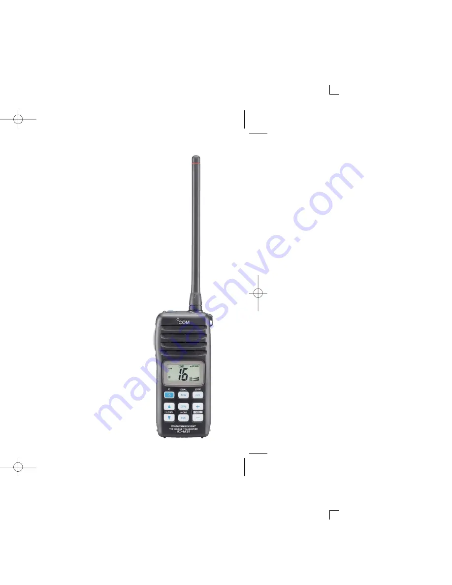
Page 3: ...annel of your choice dual watch or monitor the distress channel and another channel while receiving a channel of your choice tri watch Large easy to read LCD With dimensions of 16 H 32 W mm the IC M31 s func tion display is easy to read and shows operating conditions at a glance Backlighting and contrast can be adjusted to suit your preferences Simple operation 9 large buttons on the front panel p...
Page 4: ...be guaran teed due to the fact that the transceiver may be cracked or the waterproof seal damaged etc MAKE SURE the flexible antenna top panel and battery pack are securely attached to the transceiver and that the an tenna top panel and battery pack are dry before attachment Exposing the inside of the transceiver to water will result in serious damage to the transceiver Icom Icom Inc and the logo ...
Page 5: ... 15 Description 15 Operation 15 7 SET MODE 16 20 SET mode programming 16 SET mode items 17 8 BATTERY CHARGING 21 24 Battery charging 21 Battery cautions 21 Optional battery case 22 Optional battery chargers 23 9 OPTIONAL SWIVEL BELT CLIP 25 26 MB 87 contents 25 To attach 25 To detach 26 10 TROUBLESHOOTING 27 11 CHANNEL LIST 28 12 SPECIFICATIONS AND OPTIONS 29 13 DOC 30 ...
Page 6: ...rator Only a licensed radio operator may operate a transceiver However non licensed individuals may talk over a transceiver if a licensed operator starts supervises ends the call and makes the necessary log entries A current copy of the applicable government rules and regu lations is only required to be on hand for vessels in which a radio telephone is compulsory However even if you are not requir...
Page 7: ... r for D Handstrap Pass the handstrap through the loop on the side of the transceiver as illustrated at right Facilitates carrying D Belt clip Attach the belt clip to the transceiver as illustrated below To attach the belt clip To remove the belt clip ...
Page 8: ...ly in the groove it may be dam aged when attaching the battery pack If the seal is damaged waterproofing is not guaranteed Make sure both the rubber seal purple is set to the groove correctly and dust or else does not adhere to it Battery pack Battery pack Rubber seal Groove Correct position Incorrect position NOTE When attaching a battery pack make sure dust or else does not adhere to the rubber ...
Page 9: ...p 15 r TRANSMIT POWER LOCK KEY H L LOCK Selects high or low power when pushed p 10 Toggles the lock function ON OFF when pushed for 1 sec p 12 t VOLUME UP DOWN KEYS VOL Adjusts the volume level p 9 After pushing SQL MONI push to adjust the squelch level p 9 y SQUELCH KEY SQL MONI Push this key then adjust the squelch level with p 9 Manually opens the squelch for monitoring the channel while pushed...
Page 10: ...mitting w BUSY INDICATOR Appears when receiving a signal or when the squelch opens p 10 blinks while monitoring p 12 e TAG CHANNEL INDICATOR p 14 Appears when a tag channel is selected r CALL CHANNEL INDICATOR p 7 Appears when the call channel is selected q e r y t w 5 3 4 i u o 2 1 0 7 6 ...
Page 11: ...evel 5 CHANNEL NUMBER READOUT Indicates the selected operating channel number In SET mode indicates the selected condition 6 CHANNEL GROUP INDICATOR p 8 I appears when International U appears when U S A U K version only ATIS appears when the channel group in which ATIS function is activated German version only 7 LOW POWER INDICATOR p 10 LOW appears when low power is selected LOW blinks when switch...
Page 12: ...hannel group for quick recall q Push 16 C for 1 sec to select the call channel in the se lected channel group CALL and the call channel number appear Each channel group may have its own call channel after pro gramming a call channel See the Call channel programming on p 11 for details w Push DIAL to return to the condition before selecting the call channel or push Y Z to select the operating chan ...
Page 13: ...8 4 BASIC OPERATION s S 2 op d in ec 4 ...
Page 14: ...choose from OP is completely open 10 is tight squelch 1 is loose squelch level When no key is pushed for 5 sec the transceiver returns to nor mal condition w Push SQL MONI again to return to normal condition CONVENIENT The squelch level adjustment key can be selected from Y Z and with following operation While pushing both SQL MONI and Y turn the power ON to set Y Z to the squelch level adjustment...
Page 15: ...om your mouth and speak into the microphone at a normal voice level NOTE The transceiver has a power save function to con serve the battery power The power save function activates automatically when no signal is received for 5 sec q Power ON e Set channel t Push to transmit y Release to receive r Set output power w Set volume w Set the squelch level w Set the squelch level Microphone ay 4 ...
Page 16: ...el in t Push 16 C to program the dis played channel as the call chan nel The call channel number stop flash ing ...
Page 17: ...ion The monitor function releases the noise squelch mute See p 18 for details of the monitor switch action Push SQL MONI for 1 sec to activate the monitor func tion blinks and audio is emitted MONI Push for 1 sec Blinks while the monitor function is used 4 ...
Page 18: ...anning such as digital communications Choose priority or normal scan in SET mode p 17 e n n 6 NORMAL SCAN Normal scan like priority scan searches through all tag channels in sequence However unlike priority scan Chan nel 16 is not checked unless Channel 16 is set as a tag channel CH 01 CH 02 CH 88 CH 05 CH 04 CH 03 ...
Page 19: ...SCAN blinks in the function display 16 appears on the sub channel readout during priority scan When a signal is received scan pauses until the signal disap pears or resumes after pausing 5 sec according to scan resume timer setting Channel 16 is still monitored during priority scan Push Y Z to check the scanning tag channels change the scanning direction or resume the scan manually e To stop the s...
Page 20: ... watch A beep tone sounds when a signal is received on Channel 16 Tri watch becomes dualwatch when receiving a signal on the call channel e To cancel dualwatch tri watch push SCN DUAL again h h s i Example Operating tri watch on INT channel 07 Tri watch starts Push for 1 sec Signal is received on the call channel Signal received on Channel 16 takes priority Tri watch resumes after the signal disap...
Page 21: ...ush SQL MONI or SQL MONI and Y to select the de sired item if necessary r Push Y Z to select the desired condition of the item t To exit SET mode push 16 C ttings and the selected item is displayed in the dotted circle Auto scan Scan resume timer Dual Tri watch Auto backlight Power save LCD contrast Monitor switch MONI Push MONI Push and 6 7 ...
Page 22: ...in sequence while monitoring Channel 16 D Scan resume timer St The scan resume timer can be set as a pause OFF or timer scan ON When OFF is selected the scan pauses until a received signal disappears When ON is selected the scan pauses for 5 sec after receiving a signal and then resumes even if the signal has been received Push Scan resume timer OFF default Scan resume timer ON Push Normal scan Pr...
Page 23: ... pushing and holding SQL MONI default Ho HOLD After pushing the SQL MONI for 1 sec the squelch opens and emits audio even SQL MONI is released To close the squelch push any key D Automatic backlighting bL This function is convenient for nighttime operation The auto matic backlighting turns the backlighting ON when any key except for PTT is pushed The backlighting is automatically turned OFF after ...
Page 24: ...ing items are checked after the power is turned ON then it switches to operation mode Temperature Outside of 25 C to 65 C approx Connected battery voltage Water intrusion When error messages as shown below are displayed see troubleshooting for advice p 27 Temperature error Battery voltage error Water intrusion error Push Self check OFF default Self check ON ...
Page 25: ...n function Dual Tri watch function Monitor switch action Automatic backlighting LCD contrast selection Power save function Self check function OFF ON US OFF ON OFF ON OFF ON Dual Tri Push Hold OFF ON OFF ON OFF ON OFF ON OFF ON bP Pr St AS dt Sq bL LC PS SC bt Battery voltage indicator SET MODE LIST Default setting 7 ...
Page 26: ...eries in water If the battery pack be comes wet be sure to wipe it dry BEFORE attaching it to the transceiver NEVER short the terminals of the battery pack Also cur rent may flow into nearby metal objects such as a necklace etc Therefore be careful when carrying with or placing near metal objects carrying in handbags etc If your battery pack seem to have no capacity even after being charged comple...
Page 27: ...strated below q Remove the battery case from the transceiver w Install 6 AA R6 size alkaline batteries Be sure to observe the correct polarity CAUTION When installing batteries make sure they are all the same brand type and capacity Also do not mix new and old batteries together Keep battery contacts clean It s a good idea to clean bat tery terminals once a week ws ...
Page 28: ... w Connect the plugs of the BC 119N 121N to the AD 103 desktop charger adapter with the connector then install the adapter into the charger with the supplied screws Screws supplied with the charger adapter ...
Page 29: ...o be charged simultaneously The following are additionally re quired Six AD 103 charger adapters An AC adapter BC 124 or the DC power cable OPC 656 AD 103 charger adapters are installed in each slot IC M31 BP 224 DC power cable OPC 656 Connect with the DC power supply 13 8 V at least 7 A AC adapter purchased separately ed 8 ...
Page 30: ...1 1 he w Clip the belt clip to a part of your belt and insert the trans ceiver into the belt clip until the base clip fitting into the groove e Once the transceiver is locked in place it swivels as illus trated below ...
Page 31: ...26 9 OPTIONAL SWIVEL BELT CLIP 9 the NG LT elt ally ...
Page 32: ...ect Push H L LOCK to select high power Push H L LOCK for 1 sec to cancel the function p 12 mmed Set the desired channels as TAG channels p 14 Set the beep tones to ON Fix Beep User Beep in SET mode p 17 of 25 C to Leave the transceiver at room temperature for a while Turn the power ON to check if the internal temperature has returned to normal s voltage is Verify the battery voltage is correct ver...
Page 33: ...161 575 57 850 60 625 70 156 525 80 157 025 161 625 61 156 075 160 675 MHz CH Frequency MHz CH Frequency MHz CH Frequency MHz eceive Transmit Receive Transmit Receive Transmit Receive 57 100 64A 156 225 156 225 77 156 875 156 875 86 157 325 161 925 57 150 65A 156 275 156 275 78A 156 925 156 925 86A 157 325 157 325 61 800 66A 156 325 156 325 79A 156 975 156 975 87 157 375 161 975 61 850 67 156 375 ...
Page 34: ...ry packs six AD 103 s are re quired simultaneously An AC adapter should be purchased sepa rately Charging time approx 1 5 to 2 hours BC 150 DESKTOP CHARGER BC 147E AC ADAPTER Used for regular charging of battery pack Charging time approx 8 hours MB 68 BELT CLIP The same as supplied with the transceiver MB 74N BELT CLIP Exclusive alligator type belt clip MB 87 SWIVEL BELT CLIP Belt clip for swivel ...
Page 35: ...ck that you have the correct version of this radio or the cor rect programming of this radio to comply with na tional licensing requirement 12 13 DECLARATION OF CONFORMITY RANSCEIVER Signature Authorized representative name Place and date of issue Düsseldorf 29th Aug 2003 s equipment complies with the Telecommunications Terminal t any applicable Essential Test ed 0560 with the following harmonised...
Page 36: ...1 1 32 Kamiminami Hirano ku Osaka 547 0003 Japan ...