8
2
INSTALLATION AND CONNECTIONS
■
Power
Make sure the [POWER] switch is turned OFF when
connecting an AC power cable and a backup battery
(emergency power supply).
The IC-FR4000 series can operate with an AC or DC
power supply. If AC power is interrupted when operat-
ing the repeater with an AC power supply, power is au-
tomatically provided to the [BATTERY] terminals.
NOTE:
When repeat to turn the repeater ON and
OFF quickly, the repeater may not turn ON. In this
case turn OFF the power switch and wait for a
while, then turning power ON again.
D
IN AC OPERATION
• The [DC] indicator turns OFF.
• Use the supplied AC power cable for connection to a
domestic AC outlet.
• Extension cords should not be used unless ab-
solutely necessary. Using improper extension cords
could result in fire risk.
• Usually the battery is continuously charged with a
small amount of current from an AC power supply
through the regulator circuit in the repeater. Dis-
charging is therefore prevented even if the battery is
not used for a long time.
D
IN DC OPERATION
CAUTION:
Voltages greater than 16 V DC will dam-
age the repeater. Check the source voltage before
connecting the power cable.
• The [DC] indicator lights up green.
•
DO NOT
place the backup battery on or near the re-
peater. Lead-acid batteries should be placed at least
5 m (16.4 ft.) away from the repeater. Use a heavy
duty cable to make the connection and be sure both
the positive (red) and negative (black) terminals are
correctly connected.
• After the battery is connected and the [POWER]
switch is ON, the repeater continuously supplies ap-
prox. 1 A for charging the battery. If the repeater
stops functioning while connected to the battery, dis-
connect the battery, recharge it, then connect the bat-
tery to continue operation after the battery is charged.
During repeater transmission, approx. 17 A of battery
power is consumed.
■
Mounting the repeater
D
Using the optional MB-78
An optional MB-78
19
INCH RACK MOUNT BRACKET
is
available for mounting the repeater into a 19 inch rack.
The MB-78 can install the repeater’s bottom side and
top side.
• Bottom side installation
q
Remove the 2 screws (M4
×
8) from both side of the
side panel (front-end).
w
Attach the MB-78 to the bottom side of the repeater.
e
Tighten the 1 supplied screws (M4
×
8) and 2 re-
moved screws to each side. (6 screws at total)
r
The completed bottom side installation should look
like below.
Summary of Contents for IC-FR4000 Series
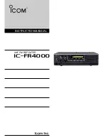
Page 1: ...INSTRUCTION MANUAL UHF FM REPEATER iFR4000...
Page 19: ...MEMO...


