background image

INSTRUCTION MANUAL

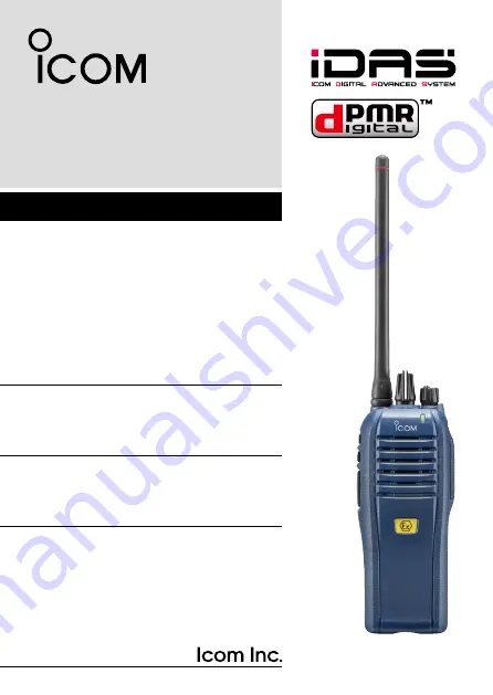
The photo shows the 
VHF transceiver.

VHF DIGITAL/ANALOG TRANSCEIVER

iF3200DEX

Series

UHF DIGITAL/ANALOG TRANSCEIVER

iF4200DEX

Series

This device complies with Part 15 of the FCC Rules. Op-
eration is subject to the condition that this device does not 
cause harmful interference.

Summary of Contents for IC-F4200DEX

Page 1: ...sceiver VHF DIGITAL ANALOG TRANSCEIVER iF3200DEX Series UHF DIGITAL ANALOG TRANSCEIVER iF4200DEX Series This device complies with Part 15 of the FCC Rules Op eration is subject to the condition that t...

Page 2: ...n manual includes some functions which are us able only when they are preset by your dealer Ask your dealer for details To use in explosive atmospheres read the leaflet SAFETY MANUAL comes with the tr...

Page 3: ...ice coding Technology embodied in this product is protected by intellectual property rights including patent rights copyrights and trade secrets of Digital Voice Systems Inc This voice coding Technolo...

Page 4: ...cm 2 to 4 inches away from the lips and the transceiver is vertical R WARNING NEVER operate the transceiver with a headset or other audio accessories at high volume levels Hearing experts advise agai...

Page 5: ...eiver will become hot when operating it continuously for long periods of time BE CAREFUL The transceiver meets IP67 requirements for dust tight and waterproof protection However once the transceiver h...

Page 6: ...panels 5 LED indicator 7 Programmable function keys 10 3 BASIC OPERATION 14 26 Turning ON the power 14 Channel selection 15 Call procedure 16 Receiving and transmitting 17 Setting the microphone gain...

Page 7: ...eceiving a call 27 Transmitting a call 30 Status message transmission 32 Scrambler function 32 5 BATTERY CHARGING 33 38 Caution 33 Battery charger 37 6 SPEAKER MICROPHONE 39 40 Optional HM 203EX descr...

Page 8: ...na other than listed on page 42 Transmitting without an antenna may damage the transceiver Supplied accessories The following accessories are supplied with the transceiver 1 1 ACCESSORIES Battery pack...

Page 9: ...ip Slide the belt clip in the direction of the arrow until the belt clip locks in place and makes a click sound Belt clip To detach the belt clip Remove the battery pack from the transceiver if it is...

Page 10: ...lick sound To remove the battery pack Push the battery release button in the direction of the arrow w as shown below The battery pack can be removed NEVER remove or attach the battery pack when the tr...

Page 11: ...h the connector cover when optional equipment is not used To attach the connector cover Attach the cover to the multi q q connector Tighten the screw w w To detach the connector cover q Remove the scr...

Page 12: ...KEY tPTT SWITCH iANTENNA CONNECTOR ROTARY SELECTOR LED INDICATOR VOLUME CONTROL MULTI CONNECTOR q ROTARY SELECTOR Rotate to select the preprogrammed memory channels or scan lists depending on the prep...

Page 13: ...ceived depending on the presetting r MULTI CONNECTOR Connect optional equipment t PTT SWITCH PTT Hold down to transmit release to receive y LOWER KEY Lower u UPPER KEY Upper A desired function can be...

Page 14: ...en when in the noise squelch opens On a digital or mixed channel lights Green while detecting a frame synchronization G Call LED Turns ON when receiving a matched 2 5 tone or receiving a Sta tus or SD...

Page 15: ...e is released Received signal will be heard O O Fast Slow scan or voting Blinks when scanning for a channel to search for a signal or a repeater to register on G G Low Battery 1 You should charge the...

Page 16: ...tartup R O G R O G TX inhibit Blinks while in the TX inhibit mode such as when the TOT or Lock out function is activated R O O O Emergency Blinks when an Emergency call was received G O R G O R G O R...

Page 17: ...IORITY B CHANNEL Push to select the Priority A or Priority B channel PRIORITY A CHANNEL REWRITE PRIORITY B CHANNEL REWRITE Push to select the Priority A or Priority B channel Hold down Prio A Rewrite...

Page 18: ...y return to the mute condition after a specified time period Depending on the presetting holding down this key for 1 second cancels a scan LOCK Hold down to electronically lock all programmable keys e...

Page 19: ...ansmit an emergency call The emergency call transmits with beeps and the LED lights red The transceiver can transmit an emergency call without the beep sounding and the LED indicator lighting Ask your...

Page 20: ...d until the power is turned OFF SCRAMBLER Hold down for 1 second to turn ON the Voice Scrambler function while operating in the digital mode Push to turn OFF the Voice Scrambler function ANNOUNCE Push...

Page 21: ...4 5 6 7 8 9 10 11 12 13 14 15 16 17 18 19 20 Turning ON the power Prior to using the transceiver for the first time the battery pack must be fully charged for optimum life and operation p 33 Rotate VO...

Page 22: ...io A Prio B Prio A Rewrite or Prio B Rewrite AUTOMATIC SCAN TYPE Selecting a channel is not necessary When turning ON the power the transceiver automatically starts scanning Scanning stops when a sign...

Page 23: ...ective calling system which allows you to call only specific station s and prevents unwanted stations from contacting you Select a desired TX code channel or 2 5 tone code according to q q your System...

Page 24: ...stening level NOTE When a matched RX code signal is received the trans ceiver automatically transmits its microphone audio for a speci fied time period depending on the presetting Ask your dealer for...

Page 25: ...received The selected channel is a receive only channel Time out timer After continuously transmitting longer than the preprogrammed time period the time out timer activates and stops further transmi...

Page 26: ...l stun kill or revive your transceiver When the Stun command is received a beep sounds and the transceiver becomes unusable Receiving a Revive command is necessary to operate the transceiver again in...

Page 27: ...ge is 1 mini mum to 4 maximum A beep sounds after pushing Upper or Lower An error beep sounds if you try to decrease more than 1 or try to increase more than 4 Therefore you can determine the current...

Page 28: ...uelch or push Lower to decrease the squelch level loose squelch The adjustable range is 0 loose squelch to 9 tight squelch A beep sounds after pushing Upper or Lower An error beep sounds if you try to...

Page 29: ...hange the r r beep level or push Lower to turn the beep function ON or OFF The adjustable range is 1 to 5 or 1 Linked to 5 Linked A beep sounds after pushing Upper or Lower Therefore you can determine...

Page 30: ...ustment mode Push Upper to increase or r r push Lower to decrease the Ringer level The adjustable range is 1 to 5 or 1 Linked to 5 Linked A beep sounds after pushing Upper or Lower Therefore you can d...

Page 31: ...wer automatically switches to Low 1 pp 8 11 Push High Low to select the transmit output power level One beep sounds when Low 1 is selected Two beeps sound when Low 2 is selected Three beeps sound when...

Page 32: ...pending on the presetting Ask your dealer for details Hold down Lone Worker for 1 second to turn ON the Lone q q Worker function w w Push Lone Worker to turn OFF the Lone Worker function Man Down Emer...

Page 33: ...cancel the emergency call hold down Emergency again before transmitting the call If your transceiver is programmed for Silent operation you can transmit an Emergency call without the beep sounding an...

Page 34: ...ed Receiving a call Receiving an Individual call D D When an Individual call is received q q The transceiver will automatically transmit a return signal The LED indicator blinks orange Beeps sound and...

Page 35: ...ual Stun or Kill call is received the transceiver will au tomatically transmit an acknowledgement and then you cannot re ceive or transmit Reception may be available depending on the presetting of the...

Page 36: ...he call will be ignored and the transceiver will not transmit its microphone au dio Receiving an Emergency call D D When an Emergency call is received The transceiver will automatically transmit a ret...

Page 37: ...q nel keys MR CH 1 to MR CH 4 to select a desired channel Individual ID or Talkgroup ID depending on the presetting Push PTT or Call to make a Voice call w w The LED indicator lights red while transm...

Page 38: ...dividual or Talkgroup call types of emergency calls can be pre set If the call type is not preset the default or selected call type is used If you want to cancel the emergency call hold down Emergency...

Page 39: ...ON or OFF Select a status message to be transmitted in Power ON Status or Power OFF Status items respectively Select a target station ID in Power Status ID Scrambler function The voice scrambler func...

Page 40: ...R DO NOT hammer or otherwise impact the battery Do not use the battery if it has been severely impacted or dropped or if the battery has been subjected to heavy pressure Battery damage may not be visi...

Page 41: ...t is not specified in this instruction manual R DANGER If fluid from inside the battery gets in your eyes blind ness can result Rinse your eyes with clean water without rubbing them and see a doctor i...

Page 42: ...om the radio after discharging You may use the battery until the remaining capacity is about half then keep it safely in a cool dry place within the temperature range as shown below 20 C to 50 C 4 F t...

Page 43: ...uing to charge the battery beyond the specified time limit may cause a fire overheat ing or the battery may rupture R WARNING NEVER insert the transceiver battery attached to the transceiver into the...

Page 44: ...g time Approximately 2 5 hours for the BP 277EX Following item is additionally required An AC adapter not supplied with some versions Status indicator Lights orange While charging Lights green Chargin...

Page 45: ...8 5 BATTERY CHARGING 1 2 3 4 5 6 7 8 9 10 11 12 13 14 15 16 17 18 19 20 IMPORTANT Ensure the grooves on the battery pack are correctly aligned with the guide rails inside the charger Guide rail Groove...

Page 46: ...mi crophone NEVER immerse the connector in water If the connector becomes wet be sure to dry it BEFORE connecting it to the transceiver NOTE The microphone is located at the top of the speaker mi crop...

Page 47: ...ector cover attached to the trans ceiver when the speaker microphone is not in use p 4 Water will not get into the transceiver even if the cover is not at tached however the terminals pins will become...

Page 48: ...e power save function is turned ON and the operating time is calculated under the following conditions TX RX standby 5 5 90 D BELT CLIP MB 94EX belt clip Exclusive alligator type belt clip D CHARGER B...

Page 49: ...aker microphone Combination speaker microphone that provides convenient op eration while hanging the transceiver on your belt Approved Icom optional equipment is designed for optimal performance when...

Page 50: ...in 65 Edition 97 01 Supplement C Evaluating Compliance with FCC Guidelines for Human Exposure to Radio Frequency Electromagnetic Fields American National Standards Institute C95 1 1992 IEEE Standard f...

Page 51: ...ng the radio to your belt etc to ensure FCC and IC RF exposure compliance requirements are not exceeded To provide the recipients of your transmission the best sound quality hold the antenna at least...

Page 52: ...ent C dition 97 01 du Bulletin OET n 65 de la FCC Eva luating Compliance with FCC Guidelines for Human Exposure to Radio Frequency Electromagnetic Fields Norme de l American National Standards Institu...

Page 53: ...vous attachez la radio votre ceinture ou autre chose de fa on vous assurer de ne pas provoquer une exposi tion aux RF sup rieure aux limites fix es par la FCC et d IC Pour offrir vos interlocuteurs la...

Page 54: ...t This equipment generates uses and can radiate radio frequency energy and if not installed and used in accordance with the instruction manual may cause harmful interference to ra dio communications O...

Page 55: ...48 MEMO 1 2 3 4 5 6 7 8 9 10 11 12 13 14 15 16 17 18 19 20...

Page 56: ...1 1 32 Kamiminami Hirano ku Osaka 547 0003 Japan A 7100D 1EX Printed in Japan 2013 Icom Inc Printed on recycled paper with soy ink...

Reviews: