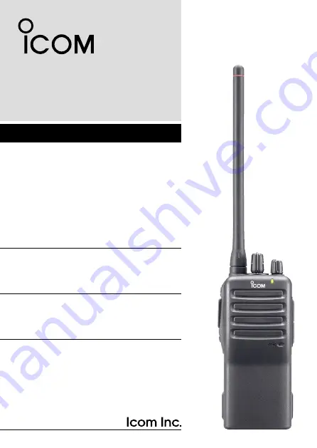
INSTRUCTION MANUAL
This device complies with Part 15 of the FCC rules. Operation is subject to the condition that this device does not cause harmful inter-ference.
UHF TRANSCEIVER
iF24/S
VHF TRANSCEIVER
iF14/S
iF26-L
Page 1: ...TION MANUAL This device complies with Part 15 of the FCC rules Operation is subject to the condition that this device does not cause harmful inter ference UHF TRANSCEIVER iF24 S VHF TRANSCEIVER iF14 S...
Page 2: ...ting Compliance with FCC Guidelines for Human Exposure to Radio Frequency Electromagnetic Fields American National Standards Institute C95 1 1992 IEEE Standard for Safety Levels with Respect to Human...
Page 3: ...e requirements are not exceeded To provide the recipients of your transmission the best sound qual ity hold the antenna at least 5 cm 2 inches from your mouth and slightly off to one side The informat...
Page 4: ...WARNING Personal injury fire hazard or electric shock may occur CAUTION Equipment damage may occur NOTE If disregarded inconvenience only No risk of personal injury fire or electric shock OPERATING NO...
Page 5: ...NOT use or place the transceiver in direct sunlight or in areas with temperatures below 22 F 30 C or above 140 F 60 C DO NOT modify the transceiver for any reason MAKE SURE the flexible antenna and ba...
Page 6: ...12 Channel selection 12 3 CONVENTIONAL OPERATION 12 17 Call procedure 13 Receiving and transmitting 14 Scrambler function 16 Setting the squelch level 16 Man Down Emergency Call 17 Emergency Call 17...
Page 7: ...ories The following accessories are supplied Qty q Flexible antenna 1 w Battery pack 1 e Belt clip 1 r Unit cover double sided tape 1 t Jack cover with screws 1 set Use the unit cover as a spare Ask y...
Page 8: ...ssory attachments D Flexible antenna Connect the supplied flexible antenna to the antenna connector CAUTION NEVER HOLD the antenna when carrying the transceiver Transmitting without an antenna may dam...
Page 9: ...y pack until the battery release button makes a click sound To release the battery pack Push the battery release button in the direction of the arrow w as shown below The battery pack is then released...
Page 10: ...aker microphone is not used To attach the jack cover q Attach the jack cover to the SP MIC connector w Tighten the screws To detach the jack cover q Unscrew the screws with a phillips screwdriver w De...
Page 11: ...ack if it is attached w Slide the belt clip in the direction of the arrow until the belt clip is locked and makes a click sound To detach the belt clip q Release the battery pack if it is attached w P...
Page 12: ...S IC F14 F24 F26 L q CHANNEL SW SELECTOR IC F14S F24S Toggle the channel switch to select the pre programmed channel 1 or 2 IC F14 F24 F26 L Rotate the channel selector to select the pre programmed me...
Page 13: ...nnects the optional speaker microphone earphone etc SP MIC jack cover NOTE Attach the SP MIC jack cover when the optional equip ment is not used p 4 t DEALER PROGRAMMABLE KEY Lower The desired functio...
Page 14: ...TX Turns Red while transmitting a signal RX Turns Green while receiving a signal Call LED ON When receiving a matched 2 5 tone Call LED Blink When receiving a matched 2 5 tone Fast Slow scan Blinks wh...
Page 15: ...e of trans mission during scan cancels scanning When the power ON scan function is turned ON Push to pause scanning Scanning resumes after passing a specified time period In case of transmission durin...
Page 16: ...cified period LOCK KEY Push and hold to electronically lock all programmable keys except the following Call incl Call A and Call B Moni Audi and Emergency keys OUTPUT POWER SELECTION KEY Select the tr...
Page 17: ...ent is pushed an emergency call is transmitted with no beep emission If you want to cancel the emergency call push or push and hold the key again before transmitting the call The emergency call is tra...
Page 18: ...s 3 and 4 are avail able when MR CH 3 and MR CH 4 keys are assigned IC F14 F24 F26 L Rotate CHANNEL SELECTOR to se lect the desired operating channel in sequence or push one of MR CH 1 to MR CH 4 key...
Page 19: ...all specific station s only and prevent unwanted stations from contacting you q Select the desired TX code channel or 2 5 tone code according to your System Operator s instructions This may not be nec...
Page 20: ...d MR CH 4 keys are assigned e When receiving a call adjust the audio output level to a com fortable listening level Transmitting Wait for the channel to become clear to avoid interference q While push...
Page 21: ...ammed time period the time out timer activates and causes the transceiver to stop trans mitting Penalty timer Once the time out timer activates transmission is further inhibited for a period determine...
Page 22: ...Push Scrambler to turn the scrambler function OFF Setting the squelch level The squelch circuit mutes the received audio signal depending on the signal strength q While pushing PTT and Lower rotate V...
Page 23: ...ed IMPORTANT Set an emergency channel individually to pro vide certain emergency call operation is recommended Emergency Call The emergency call can be performed using the Emergency Single or Emergenc...
Page 24: ...instru ment and insert into the hollow of the chassis then lift and take away the unit cover The removed cover cannot be used again e Install the unit as shown below This illustration is described wi...
Page 25: ...r as shown at left Optional unit installation e Cut the pattern on the PCB at the TX mic circuit MIC and RX AF circuit DISC as shown below r Install the scrambler unit as shown at left Optional unit i...
Page 26: ...ected to heavy pressure Battery damage may not be visible on the outside of the case Even if the surface of the battery does not show cracks or any other damage the cells inside the battery may ruptur...
Page 27: ...he body that comes into contact with fluid from inside the battery WARNING NEVER put the battery in a microwave oven high pressure container or in an induction heating cooker This could cause a fire o...
Page 28: ...remove the battery from the battery charger Continuing to charge the battery beyond the specified time limit may cause a fire over heating or the battery may rupture WARNING NEVER insert the transcei...
Page 29: ...dapter may be supplied depending on version or the DC power cable OPC 515L CP 17L is additionally required AC adapter Not supplied with some versions Optional OPC 515L for 13 8 V power source or CP 17...
Page 30: ...be supplied depending on version or the DC power cable OPC 515L CP 17L is additionally required AC adapter Not supplied with some versions Optional OPC 515L for 13 8 V power source or CP 17L for 12 V...
Page 31: ...the BC 119N or BC 121N before battery charging Connect the AD 106 charger adapter and the BC 119N BC 121N as below then install the AD 106 into the holder space of the BC 119N or BC 121N with the sup...
Page 32: ...supplied with BC 119N depending on version or the DC power cable OPC 515L CP 17L AD 106 charger adapter is installed in BC 119N AC adapter Not supplied with some versions Optional OPC 515L for 13 8 V...
Page 33: ...following items are additionally required Six AD 106 An AC adapter BC 157 or the DC power cable OPC 656 AC adapter Purchase separately AD 106 charger adapters are installed in each slot DC power cable...
Page 34: ...lose r Hook the battery cover release hook until it makes a click sound t Fig 3 CAUTION When installing batteries make sure they are all the same brand type and capacity Also do not mix new and old ba...
Page 35: ...29 6 BATTERY CASE 1 2 3 4 5 6 7 8 9 10 11 12 13 14 15 16 17 18 19 20 q BP 240 w Fig 1 Fig 2 Fig 3 e r t...
Page 36: ...IP MB 93 contents Qty q Belt clip 1 w Base clip 1 To attach q Release the battery pack if it is attached p 3 w Slide the base clip in the direction of the arrow until the base clip is locked and makes...
Page 37: ...o a part of your belt And insert the transceiver into the belt clip until the base clip inserted fully into the groove r Once the transceiver is locked in place it swivels as illustrated below 1 2 3 4...
Page 38: ...32 7 SWIVEL BELT CLIP To detach q Turn the transceiver upside down in the direction of the arrow and pull out from the belt clip...
Page 39: ...n of the arrow w q w CAUTION HOLD THE TRANSCEIVER TIGHTLY WHEN HANGING OR DETACHING THE TRANSCEIVER FROM THE BELT CLIP Otherwise the transceiver may not be attached to the holder or swivel properly if...
Page 40: ...arging time approx 3 hours when BP 232N is attached BC 121N multi charger AD 106 charger adapter 6 pcs BC 157 ac adapter For rapid charging of up to 6 battery packs six AD 106 s are re quired simultan...
Page 41: ...he transceiver MB 96N 96F leather belt hanger D DC CABLES CP 17L cigarette lighter cable Allows charging of the battery pack through a 12 V cigarette lighter socket For BC 119N OPC 515L OPC 656 dc pow...
Page 42: ...SC25V FA SC55V antennas FA SC01U 350 400 MHz FA SC25U 400 430 MHz FA SC57U 430 470 MHz FA SC72U 470 520 MHz FA SC25V 136 155 MHz FA SC55V 146 174 MHz FA SC61VC FA SC61UC cut antennas FA SC61VC 136 17...
Page 43: ...ns to receive when you stop speaking Features Straight type head SP MIC plug equipped Water resistant construction Durable construction Equipped with a PTT switch and revolving clip MIC VOX gain adjus...
Page 44: ...harmful interference to radio communications However there is no guarantee that interference will not occur in a particular installation If this equipment does cause harmful inter ference to radio or...
Page 45: ...MEMO 1 2 3 4 5 6 7 8 9 10 11 12 13 14 15 16 17 18 19 20...
Page 46: ...MEMO...
Page 47: ...MEMO 1 2 3 4 5 6 7 8 9 10 11 12 13 14 15 16 17 18 19 20...
Page 48: ...1 1 32 Kamiminami Hirano ku Osaka 547 0003 Japan A 6369D 1EX i Printed in Japan 2004 2009 Icom Inc Printed on recycled paper with soy ink...