Figure 2. – PLL Board Location
The connection points are shown in Figure 3. The green connections are on the left edge of the PLL board.
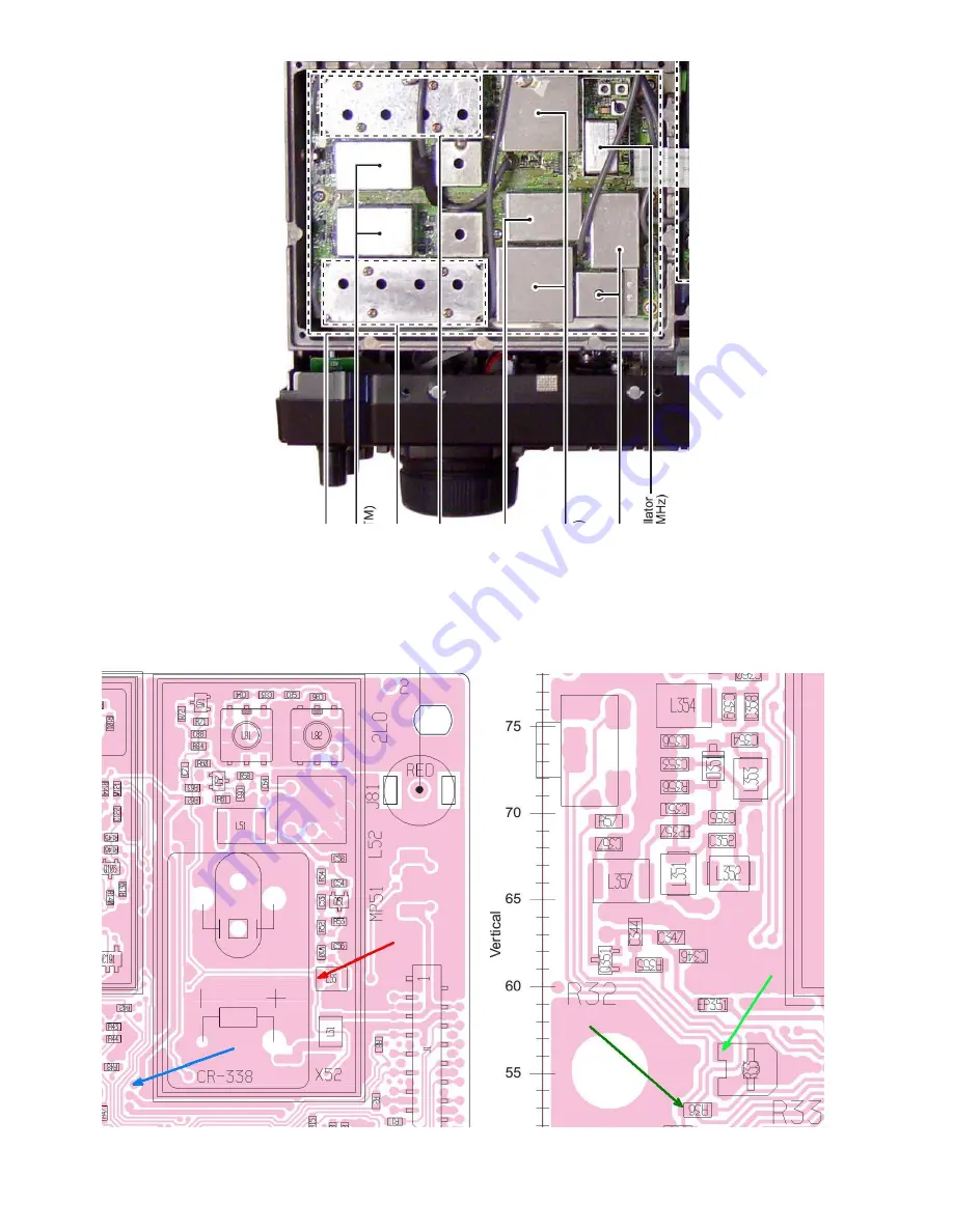
Figure 3. – PLL Board Reference Oscillator Connections
Page 1: ...actory In the case of the Icom IC 756ProIII the Reference frequency is 32 0 MHz 2 Technical Specifications Connections to the board are shown below Connection Description Specifications Test Do Not Co...
Page 2: ...ol voltage is fed back to the Reference Oscillator The Red arrow indicates where 8V is taken to power the XRef 4 Installation For this installation you will need about 300mm of very thin coax say RG17...
Page 3: ...Figure 2 PLL Board Location The connection points are shown in Figure 3 The green connections are on the left edge of the PLL board Figure 3 PLL Board Reference Oscillator Connections...
Page 4: ...in coax to the XRef Optionally an LED can be connected from the XRef Lock pin to ground to indicate when the radio is locked to 10 MHz The LED could be mounted next to the connector on the back panel...