background image

Maintenance

30

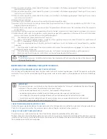
T(1) Physical verification of the intervention of the devices (as described in the following paragraph "Checking of the minimum 

level safety level switches").

T(2) Physical verification of the intervention of the devices (as described in the following paragraph "Checking of the minimum 

level safety level switches").

T(3) Physical verification of the intervention of the devices (as described in the following paragraph "Checking of the minimum 

level safety level switches").

T(4) Purge the level indicators.
T(5) Manually verify, using the selectors on the panel front, the opening of the valves.
T(6) Analysis of the water quality by taking a sample from the generator, check if it meets the specifications of EN12953-10 (see 

paragraph "Water characteristics").

T(7) Analysis of the water quality by taking a sample from the generator and check it meets the indications of the TDS automatic 

control device.

T(8) Carefully check the load system, correspondence of level in the glass indicators with the parameters described in this manual.
T(9) Verification of safety valves by applying a sample pressure gauge to the generator, as reference of the exact intervention 

pressure. Verifications must be performed by qualified personnel.

T(10) 

Check correct seal, grease, lubricate where necessary.

T(11) 

Analysis of the water quality by taking a sample from the supply/treatment system, check if it meets the specifications of 

EN12953-10 (see paragraph "Water characteristics").

T(12) 

Check the proper operation of all safety, electric and electronic circuits. Verifications must be performed by qualified 

personnel.

T(13) 

Check the correct indications of the instrumentation with sample thermometers/pressure gauges. Verifications must be 

performed by qualified personnel.

T(14) 

Check the burner, combustion control, safety devices. Verifications must be performed by qualified personnel.

T(15) 

Bench check of the safety devices. Verifications must be performed by qualified personnel.

ATTENTION

The electronic level relays inside the electrical panel must be replaced after 8 years of operation as they have reached 
the end of their life-span.

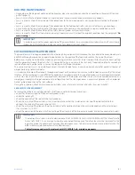
METHODS FOR CHECKING THE SAFETY DEVICES

CHECKING OF THE MINIMUM LEVEL SAFETY LEVEL SWITCHES

Stand in front of the electrical panel, leave the steam outlet valve with removal regulator open, turn off the pump by putting the 
selector to "0", wait for the natural lowering of the generator water level. To speed up the operation act on the mud discharge 
valve.

IMPORTANT

The two safety devices must intervene when the water level reaches the "minimum" indicated on the side of the glass 
indicators. Otherwise, check the entire level switch consisting of:


electronic level regulator; check it is intact and, if not, proceed with replacement


connection cable between electrical panel and probe; possible interruption and/or short circuit


level probe; check for possible breakage of the ceramic part and consequent loss of electrical insulation


level dipstick; possible scaling that prevents water-probe current pass or possible detachment of the dipstick.

If the check is positive, place the pump command to "AUT".

CHECK THE MAXIMUM LEVEL SWITCH (IF ANY)

Position the pump selector located on the electrical panel in the MAN position and wait for the water level in the generator to rise.
Check that the pump stops when the maximum point visible in the glass indicator has been reached.

CHECK OF THE SAFETY PRESSURE SWITCH

The safety pressure switch calibration must be at least 0.5 bar below the calibration of the safety valves.
To check the correct intervention of the safety pressure switch, it is necessary to increase the calibration of the adjustment pressure 
switch(es) and ensure the switch-off of the burner and activation of the block on the boiler electrical panel by visually following 
the indication given by the pressure gauge.

Summary of Contents for SIXEN 1000

Page 1: ...SIXEN_350_5000_EN Ed 06 07 2018 EN Low pressure reverse flame steam boiler SIXEN INSTALLATION USE AND MAINTENANCE MANUAL ...

Page 2: ...el Installation 17 Product receipt 18 Handling 19 Installation room 19 Positioning 19 Room ventilation 20 System cleaning 20 Hydraulic connections 20 Flue exhaust 21 Front door opening 21 Door opening reversal to the right 22 Front door adjustment 22 Door adjustment opening on the right 22 Turbulator assembly 23 Burner assembly 23 Electrical connections 24 Loading and supply of the generator syste...

Page 3: ... SIXEN EXP 1000 86241004 SIXEN EXP 2000 86242004 SIXEN EXP 3500 86243504 SIXEN EXP 500 86240504 SIXEN EXP 1350 86241354 SIXEN EXP 2500 86242504 SIXEN EXP 4000 86244004 SIXEN EXP 650 86240654 SIXEN EXP 1700 86241704 SIXEN EXP 3000 86243004 SIXEN EXP 5000 86245004 SIXEN EXP 800 86240804 SIXEN 15 bar SIXEN 350 86250350 SIXEN 1000 86251000 SIXEN 2000 86252000 SIXEN 3500 86253500 SIXEN 500 86250500 SIX...

Page 4: ...e attention during handling and installation Periodically check the condition of the same accessories exclusion of fractures Once installation is completed check the intervention of the safety valve by carrying out a preventive hydraulic test at the PT pressure indicated on the ID plate Make sure the safety level switch is working properly in accordance with the contents of the technical manual su...

Page 5: ...d contained fluid PROHIBITIONS d IT IS FORBIDDEN Operate electrical devices or appliances such as switches household appliances etc if you smell fuel or unburnt materials In this case ventilate the room by opening doors and windows close the fuel shut off device Perform any technical or cleaning intervention before disconnecting the appliance from the electrical power supply and wearing the Person...

Page 6: ...is properly installed and adjusted and the presence of ventilation openings in the thermal power plant are compliant with the regulations in force IDENTIFICATION Each SIXEN steam generator is identified by two different data plates Boiler body data plate it is positioned below the ICI CALDAIE logo screwed to the upper covering of the front plate this plate bears the significant data of the boiler ...

Page 7: ...N4 19 21 24 23 N2 N2 N8 N11 18 18 22 22 20 1 Electrical panel 2 Regulation pressure switch no 2 pressure switches only for EXP versions 3 Block pressure switch 4 Pressure gauge 5 1st safety level probe minimum 6 2nd safety level probe minimum 7 Level adjustment probes start stop 8 Level indicator 9 Level indicator discharge 10 Front door 11 Level test valves 12 Flame control warning light 13 Burne...

Page 8: ...0 280 330 320 370 320 370 350 400 350 400 370 420 370 420 420 470 420 470 480 530 480 530 480 530 Øb mm 225 225 225 225 280 280 320 320 360 360 360 400 400 Øc mm 250 250 300 300 350 350 400 400 450 450 500 550 600 tb ØxP 1 mm 36x1220 36x1220 36x1500 36x1500 36x1220 36x1500 36x2000 36x2000 48x2400 48x2700 48x2700 48x2700 48x2700 tb 1 n 20 26 30 40 40 58 64 72 74 74 92 102 114 Attachments Descriptio...

Page 9: ...lcapacity kW 1514 1893 2271 2650 3028 3786 Efficiencyat100 ref P C I 1 90 90 90 90 90 90 Pressuredropsonexhaustside mbar 10 6 5 9 9 10 11 Ratedpressure bar 12 15 12 15 12 15 12 15 12 15 12 15 Min maxoperatingpressure bar 12 bar version 8 11 5 bar 15 bar version 12 14 Totalcapacity l 3050 3380 4020 5000 6950 7400 Capacityatlevel l 2300 2490 2825 3600 4800 5200 Evaporating surface m2 3 14 3 43 4 12 ...

Page 10: ...m generator flow rate back pressure in combustion chamber considering also the possible resistance draught of the smoke duct the length of the combustion head must be adequate to the penetration into the combustion chamber provided by ICI and shown in the table the length and shape of the flame must be suitable to the flame inversion combustion chambers The burner manufacturers have this informati...

Page 11: ...tions safety protection and control measures adopted a specific declaration prepared in accordance with art 2 of the Presidential Decree of 20 October 1998 no 403 certifying that the installation has been carried out in compliance with the operating manual the verification report where required a list of components operating under viscous flow regime or subjected to cycle fatigue if any The safety...

Page 12: ...ed the other end closed and free to move is connected to the index by a toothed sector lever system The pressure gauge is mounted on a three way valve that allows performing the following operations Communication between generator and pressure gauge normal operating position Communication between pressure gauge and the outside position needed to purge the siphon Communication between generator pre...

Page 13: ... condensate Drain must take place in the atmosphere direct the valve so as not to harm people or damage property Interception valves must not be provided The exhaust pipe must be designed in such a way that any low temperatures do not create ice that ob structs the outlet N B Bracket at no more than 1 m away m IMPORTANT The operation of the safety valves is sensitive to pressure losses that occur ...

Page 14: ... is calibrated at a higher pressure compared to the maximum one of the pressure transmitter but always lower than the opening pressure of the safety valve The safety pressure switch intervenes in case of steam pressure regulator failure adjustment pressure switch or pressure transmitter and permanently stops the burner 2 1 5 6 4 4 3 1 Sealed anti tampering cap 2 Polyamide cover 3 Stainless steel b...

Page 15: ...generator pressure and keeps it within the preset value Instructions for calibration The electric switch has three screws 1 2 4 from left to right Upon reaching the set pressure the contact 1 2 is switched into contact 1 4 Pressure switch calibration Rotate the knob 1 until setting the index of the scale 2 to the pressure value at which you wish the burner to restart Remove the cover of the pressu...

Page 16: ...ure Maintenance must be carried out when The crystal looses part of its transparency partially opaque signs of internal roughness due to erosion or corrosion as it involves loss of geometry and reading becomes difficult Minimal leaks from the gaskets or shut off groups are also noticed AUTOMATIC LEVEL REGULATOR AND SAFETY LEVEL SWITCH The detection and control principle of the level is based on th...

Page 17: ...or insulation The control panel contains the following documentation declaration of conformity use and maintenance manual safety valve certificate with declaration of conformity and use and maintenance manual feed pump characteristic curve electrical diagram m IMPORTANT The instruction manual is an integral part of the appliance and so MUST be carefully read before installing and commissioning the...

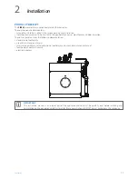
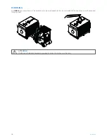
Page 18: ...he SIXEN steam generator must be handled using means adequate to the size and weight of the appliance using the provided lifting eyebolts a ATTENTION The Personal Protective Equipment required by current legislation must be used ...

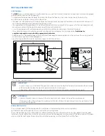
Page 19: ...rs to safely carry out the running control and maintenance of all installed components consider the possible the need to replace components that fail over time A P2 90 min 600 mm NO A P2 see Size and fittings m IMPORTANT A space is necessary at the front of the generator at least equal to the length of the tube bundle to allow the extraction of the turbulators to clean the pipes and possibly repla...

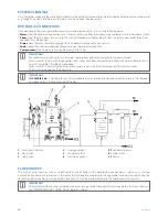
Page 20: ...e sure that the drains of the generator safety valves have been connected to a drain well in order to avoid that in case of intervention the rooms are flooded Make sure that the water and heating system pipes are not used as earthing point of the electrical system The air must be filtered with 25 µm mesh m IMPORTANT ICI CALDAIE S p A is not liable for any harm to people animals or property damage ...

Page 21: ...7 of the door DOOR WITH WRENCH FERRULES HINGE SIDE a DANGER In models equipped with wrench adjustable ferrules 8 these must always be mounted on the hinges to prevent the door from being accidentally opened through the lever 9 Proceed as follows to reverse the opening direction of the door screw the left perforated ferrules 1 so that the door seal gasket is pressed in the same way as the right par...

Page 22: ... on the ferrule 7 to adjust the distance depth wise screw the nuts 6 and block the conical washers on the mechanical tubes a DANGER When cross changing ferrules always make sure that the other two ferrules are fastened so that they hold the door Check the proper adjustment in depth ensuring that the door manually pushed up to the stop plate naturally returns remaining ajar This is to ensure the hi...

Page 23: ...ECTIONS The generators are equipped with electrical panel IP 55 protection rating complete with all connections to the various generator components already made in the factory The panel model is determined by the version of the ordered generator and the wiring diagram specific and detailed is present inside the panel The installer connections must be made by professionally qualified personnel in c...

Page 24: ...nformation of the degasser pump feed tank connection pipe and on the features of the pump itself refer to the pump manual a ATTENTION The oxygen dissolved in the water corrodes the boiler Refer to the maximum allowed values indicated in the relevant section of the technical manual Follow the table below to avoid pump cavitation problems DEGASSER TYPE Water supply temperature C Head on the intake m...

Page 25: ...ould be provided according to table 5 2 c At operating pressure 1 bar a maximum total hardness of 0 05 mmol l must be acceptable d Instead of respecting this value with intermittent operation or operation without deaerator in case of agents forming the film and or excess of oxygen the additive must be used e Organic substances are generally a mixture of various different compounds The composition ...

Page 26: ... generator water is 5 μS cm d If treatment with coordinated phosphate is used considering all other values higher concentrations of PO4 are acceptable e Organic substances are generally a mixture of various different compounds The composition of such mixtures and the behaviour of their individual components under the generator operating conditions are difficult to predict Organic substances can be...

Page 27: ... rotor rotates freely the rotation direction should be correct indicated in the rear side of the motor place the pump selector at AUT and check that there is no consent to start the burner before the water has reached the minimum level check that the pump stops when the water reaches the maximum level visible in the glass indicator press for at least 10 seconds the reset button of the water safety...

Page 28: ...rious corrosions for the generator often occur during the stop periods The operations to be carried out to store the generator correctly essentially depend on the duration of the downtime When the generator needs to be stopped for long periods dry storage can be done When the stops are for short periods or when the generator is used as a spare and must start running in a short amount of time a wet...

Page 29: ...enance bearings mechanical seal check the wear of the drain valves replace them if necessary PERIODIC VERIFICATIONS The frequency of verifications is shown in the table It MUST be strictly observed Observation and tests 6 hours 1 day 1 week 1 month 3 months 6 months 12 months Safety valves O T 9 Level indicators T 4 TDS BWD Unloading devices if present T 5 Shut off valves O T 10 Water load control...

Page 30: ...ust be performed by qualified personnel T 15 Bench check of the safety devices Verifications must be performed by qualified personnel a ATTENTION The electronic level relays inside the electrical panel must be replaced after 8 years of operation as they have reached the end of their life span METHODS FOR CHECKING THE SAFETY DEVICES CHECKING OF THE MINIMUM LEVEL SAFETY LEVEL SWITCHES Stand in front...

Page 31: ...k for any build up corrosion and other potential sources of danger pertaining to the feed water It is necessary to remove the deposits through mechanical or chemical action and use suitable tools to ensure that the actual thickness of the internal parts is not affected by corrosion Any pockmark or other type of corrosion must be scraped and cleaned with an iron brush until the metal is exposed Lea...

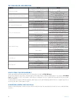
Page 32: ...panel If the problem is solved permanently replace the faulty relay Level adjustment probes short circuit Disassemble the adjustment probes to visually check the ceramic insulation Pump cavitation Head height difference between the collection vessel level and the pump insufficient in relation to the water temperature Pump intake filter cleaning Reduce resistance of the duct between collection vess...

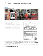
Page 33: ...ent back to a web page on which to register the data of your appliance and system by completing the indicated spaces Once registered authenticate your e mail address by clicking on the link that will be sent by e mail to the provided inbox An additional e mail will then be received with the credentials to access all services specifically developed by ICI CALDAIE S p A for those who will register t...

Page 34: ...r in order to ensure its correct operation 2 pump modulating feed Inverter With this system the level in the boiler is adjusted continuously by a PID controller that controls the rotation speed of the feed pump that is equipped with inverter The water flow rate is constantly adjusted to steam request thus avoiding the cyclical steam production that can be checked with level controls of the on off ...

Page 35: ...ency and duration of the purges must be set by the user according to the characteristics of the generator water as indicated in the technical manual of the generator The system requires compressed air GSS 72 1 72h global safety system for BX 600 BNX 1000 SIXEN 2000 and GSX 2000 generators GSS 72 1 global safety system designed and built to guarantee total safety of operation of steam generators Th...

Page 36: ... stops the boiler permanently The boiler operation is resumed only after the manual reset and the elimination of the error by the operator The system is supplied completely assembled to the boiler and tested It complies with the main European Directives Low Voltage Directive 2014 35 EU EMC Directive 2014 30 EU PED Directive 2014 68 EU Modulating level regulation system with 2 way electric valve Wi...

Page 37: ...Notes 37 7 Notes ...

Page 38: ...Notes 38 ...

Page 39: ...Notes 39 ...

Page 40: ...ICI CALDAIE SpA 37059 Fraz Campagnola di Zevio Verona Italy Via G Pascoli 38 Phone 39 0458738511 Fax 39 0458731148 info icicaldaie com www icicaldaie com ...

Reviews: