Icel Manaus GV-2005 User Manual Download Page 35


30

to


return


to


the


Burst


mode


interface.


(3) 

Press


  F3 


to


switch


to


Gated.


(4) 

Press


  F2 


to


select


Start


Phase,


define


the


Start


and


the


Stop


Point


in


a


waveform.


The


phase


varies


from

  ‐

360°


to


+360°.


For


an


Arbitrary


Waveform,


is


the


first


waveform


point.


(5) 

Press


  F5 


to


switch


between


Positive/Negative.


Set


the


Polarity


for


the


Gated


Signal.


To


Manage


File


Press


Save


function


button


to


enter


the


file


system.


You


can


view


the


waveform


files,


create


a


new


folder,


and


perform


the


file


operations


such


as


delete,


rename,


copy


and


paste.


To


Edit


the


File


Name


In


file


system,


the


user


can


edit


the


name


of


a


file


or


a


folder.


When


the


system


needs


the


user


to


input


a


name,


an


input


keyboard


will


appear.


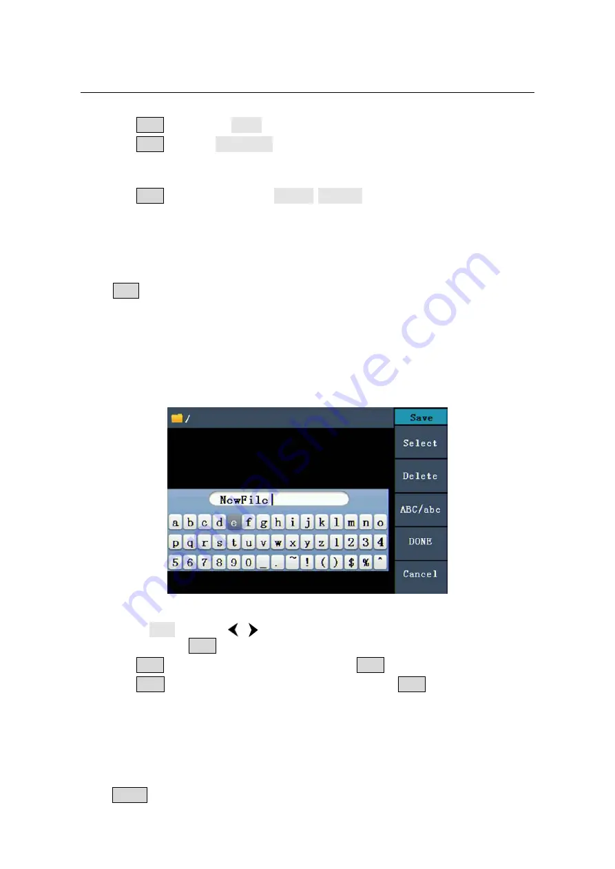
Figure 5-19: Edit the File Name 

(1) 

Turn


the


knob


or


press


/


direction


key


to


move


the


cursor


left


and


right


in


the


keyboard.


Press


  F3 


to


switch


between


capital


and


small


of


the


characters.


(2) 

Press


  F1 


to


enter


the


current


character.


Press


  F2 


to


delete


the


last


character


.


(3) 

Press


  F4 


to


finish


editing


and


save


the


file.


Press


  F5 


to


cancel


the


save


operation.


Note

:


The


length


of


file


name


is


up


to


15


characters.


To


Set


the


Utility


Function


Press


Utility


function


key


to


enter


the


Utility


Menu.


You


can


set


the


parameters


of


the


Summary of Contents for GV-2005

Page 1: ...Economical Type 1 channel Arbitrary Waveform Generator User Manual GV 2005...

Page 2: ......

Page 3: ...apply to any defect failure or damage caused by improper use or improper or inadequate maintenance and care ICEL MANAUS shall not be obligated to furnish service under this warranty a to repair damag...

Page 4: ...Output Sine Signals 11 To Set the Frequency Period 11 To Set the Amplitude 12 To Set the Offset 12 To Set the High Level 12 To Set the Low Level 12 To Output Square Signals 12 To Set the Duty Cycle 1...

Page 5: ...or 31 To Set the Screen Saver 31 To Set the Counter Only for the model with F 31 To Set Output Parameter 32 To Set the Output Load 32 To Set the System 33 Language Setting 33 Power On Setting 33 To Re...

Page 6: ...grounded The product must be grounded properly before any connection with its input or output terminal Check all Terminal Ratings To avoid fire or shock hazard check all ratings and markers of this pr...

Page 7: ...this product or other property Terms on the Product The following terms may appear on this product Danger It indicates an injury or hazard may immediately happen Warning It indicates an injury or haza...

Page 8: ...for users Features and benefits 4 inch high resolution 480 320 pixels TFT LCD display Advanced DDS technology Max Sample rate 125 MSa s Frequency resolution 1 Hz Vertical resolution 14 bits 8192 wave...

Page 9: ...Start This chapter will deal with the following topics mainly Front Rear Panel Overview User Interface Overview How to Implement General Inspection How to Adjust the Foot Stools How to Implement Power...

Page 10: ...ed to select file location or switch the character of the soft keyboard when entering file name In Sweep and N Cycle Burst if you choose Source as Manual every time you press this knob the generator w...

Page 11: ...nly for the model with F Generate the Modulated waveforms Burst Only for the model with F Generate burst for Sine Square Ramp Pulse and Arbitrary waveform Sweep Only for the model with F Sweep Sine Sq...

Page 12: ...ept an external clock signal or to accept the input signal of counter Accepting input signal of counter is only for the model with F see page 35 To Set the Counter Ext Trig Burst Fsk In connector Only...

Page 13: ...cribed in the Appendix A Enclosure of this Manual You can check whether there is any loss of accessories with reference to this description If it is found that there is any accessory lost or damaged p...

Page 14: ...hange the voltage scale of the instrument do the following steps 1 Turn off the power button at the front panel and remove the power cord 2 Regulate the Power Switch to the desired voltage scale Power...

Page 15: ...ine Signals How to Output Square Signals How to Output Ramp Signals How to Output Pulse Signals How to Output Noise Signals How to Output Arbitrary Signals How to Output DC How to Generate the Modulat...

Page 16: ...the Sine setting menu on the right The parameters of Sine waveform are Frequency Period Amplitude High Level Offset Low Level You can operate the menu by using the menu selection buttons on the right...

Page 17: ...set In Parameter 3 a cursor appears under the value of offset Use the knob or the number keys to set the desired value To Set the High Level Press F2 confirm whether the Hi_Level menu item is highligh...

Page 18: ...ut signal is set to 5Vpp amplitude and 2 5V offset When the load is 50 the output signal is set to 2 5Vpp amplitude and 1 25V offset Figure 5 3 The User Interface of Square Signal Term Explanation Dut...

Page 19: ...ating the Ramp setting menu on the right The parameters of Ramp waveform are Frequency Period Amplitude High Level Offset Low Level Symmetry You can operate the menu by using the menu selection button...

Page 20: ...ress F4 to choose Figure 5 6 Set the symmetry of Ramp signal To Output Pulse Signals Press button to call the user interface of Pulse signal the Pulse waveform parameters can be set by operating the P...

Page 21: ...0 of the falling edge amplitude Negative Pulse Width is the time span between thresholds of 50 of the falling edge amplitude to the next 50 of the rising edge amplitude Pulse Width is determined by Pe...

Page 22: ...of Noise waveform are Amplitude High Level Offset Low Level You can operate the menu by using the menu selection buttons on the right To set the Amplitude High Level Offset Low Level please refer to T...

Page 23: ...als on page 11 The Arbitrary signal consists of two types the system built in waveform and the user definable waveform Setting menu of Arbitrary signal Amplitude Load Offset Current signal Frequency P...

Page 24: ...undHalf RoundHalf wave AbsSine Absolute value of a Sine AbsSineHalf Absolute value of half a Sine SineTra Sine transverse cut SineVer Sine vertical cut NegRamp Negative ramp AttALT Gain oscillation cu...

Page 25: ...LFMPulse Linear FM pulse Rhombus Rhombus signal Cardiac Cardiac signal The User Definable Waveform Press button and press F5 to select Editable Wform Menu item Instruction Create Wform Create a new w...

Page 26: ...form 2 Enter the storage path of the desired waveform file Turn the knob or press direction key to select the desired waveform file 3 Choose Recall output How to Edit a Stored Waveform 1 Enter the ope...

Page 27: ...modulated waveform consists of two parts the Carrier Waveform and the Modulating Waveform The Carrier Waveform can only be Sine In AM the amplitude of the Carrier Waveform varies with the instantaneou...

Page 28: ...AM Frequency The range is 2 mHz 20 kHz Internal source only 7 Press F4 to set Mod Depth The range is 0 100 Term Explanation AM Frequency The frequency of modulating waveform Mod Depth The Amplitude R...

Page 29: ...elect the source If the source is External use the Ext Mod In connector in the rear panel to input the external signal then skip ahead to step 6 If you choose Internal continue to the steps below 5 Pr...

Page 30: ...u can change the parameters please refer to To Output Sine Signals on page 11 Press button again to return to the Modulation mode interface 4 Press F5 to select the source If the source is External us...

Page 31: ...form is not Sine the system will switch it to Sine automatically 3 Press button to display the waveform and parameters of the Carrier Waveform You can change the parameters please refer to To Output S...

Page 32: ...r the Sweep mode 2 Press or button to choose the waveforms Take Sine for instance press to display the waveform and parameters You can change the parameters please refer to To set signals on page 11 P...

Page 33: ...N Cycle Burst or to be controlled by external gated signals Gated Burst Bust can apply to Sine Square Ramp Pulse and Arbitrary waveforms Noise can not be used Term Explanation Burst Output Waveforms...

Page 34: ...d which will not stop until a trigger event happens the knob on the front panel is pressed Note If needed Burst Period will increase to cater to the specific number of cycles For an infinite cycle Bur...

Page 35: ...ame copy and paste To Edit the File Name In file system the user can edit the name of a file or a folder When the system needs the user to input a name an input keyboard will appear Figure 5 19 Edit t...

Page 36: ...select Sep 2 Press F2 to switch between Comma Space Off Take the Frequency parameter for instance Comma Space Off To Set the Screen Saver The screen saver will run automatically if no operation is ta...

Page 37: ...direction key to move the cursor left and right or press the number keys to input the desired value and choose the unit The range of trig levle is 2 5 V 2 5 V Press F5 to choose Back to previous menu...

Page 38: ...fault Last Default means that all the settings return to default when powered Last means that all the settings return to the last one when powered To Return to Default Setting Press Utility and choose...

Page 39: ...t Only for the model with F Default Frequency 1 kHz Count 1 Cycle Period 1 sec Phase 0 Others Default Brightness 95 Separator Comma Screen Saver time 100 minutes Load High Z Clock Source Internal Chan...

Page 40: ...d the output Voltage of the Sync output terminal is Level Low Note When the amplitude is relatively low disabling Sync Signal can reduce the distortion in output The Instructions of the Sync Signal in...

Page 41: ...he Burst when the burst starts the Sync Signal is Level High At the specific point when the Cycle Number ends the Sync Signal turns Level Low If the Waveform has a relative starting phase it may be no...

Page 42: ...a PC 2 Install the driver When the Waveform Generator is turned on a dialog will appear on the PC screen and guide you to install the USB driver The driver is in the USBDRV folder under the directory...

Page 43: ...er socket is used appropriately and in good condition the cover can be pried open with a straight screwdriver Restart the instrument after the steps above If the problem still exists please contact IC...

Page 44: ...efinable Waveform Frequency Characteristic Max sampling rate 125 MSa s Frequency resolution is 1 Hz Sine AG051 F 1 Hz 5 MHz Square 1 Hz 5 MHz Ramp 1 Hz 1MHz Pulse 1 Hz 5 MHz White Noise 5 MHz bandwidt...

Page 45: ...0 Duty Cycle 1 of period 5 ns Overshoot 5 Duty Cycle 50 fixed Ramp Linearity 0 1 of peak output typical 1 kHz 1 Vp p Symmetry 50 Symmetry 0 to 100 Pulse Pulse Width 100 ns to 1000 ks Accuracy 10 ns Ri...

Page 46: ...ting Waveforms 50 duty cycle square FSK Rate 2 mHz 100 kHz Sweep Type Linear Logarithmic Carrier Waveforms Sine Square Ramp Direction Up Down Sweep Time 1 ms to 500 s 0 1 Source Source External or Man...

Page 47: ...hare the same port as External Reference Clock Input DC coupled DC offset range 1 5 VDC 100 mHz 100 MHz 250 mVp p 5 Vp p AC DC 100 MHz 200 MHz 450 mVp p 3 Vp p AC DC AC coupled 1 Hz 100 MHz 250 mVp p...

Page 48: ...43 Dimension 235 mm 110 mm 295 mm W H D Weight 3 kg Interval Period of Adjustment One year is recommended for the calibration interval period...

Page 49: ...ing conditions require To clean the instrument exterior perform the following steps 1 Wipe the dust from the instrument surface with a soft cloth Do not make any scuffing on the transparent LCD protec...

Reviews: