


42
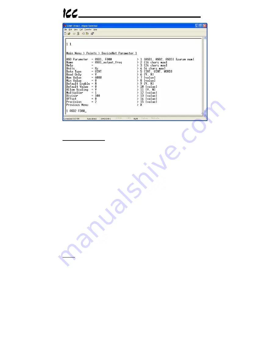
Figure 19: View/Edit a Point
Mapping Information:
Line 1 indicates the current point mapping information.
In Figure 19, it can be seen that DeviceNet Parameter 1 maps to ASD1,
parameter FD00 (the ASD’s output frequency). To change the mapping
information, enter menu selection number 1 with the additional arguments of
the device on which the data object resides and the data object index. For
example, the bottom of Figure 19 shows an example of changing DeviceNet
parameter 1’s mapping to ASD2 (the device on which the data object resides),
ASD parameter FD00 (the data object index). Again, the semantics of the
menu prompt and mapping modification entry string will vary depending on the
secondary network. A similar line 1 menu prompt when a Modbus secondary
network is chosen would be displayed as “
> 1 [ID num] [reg num]
”, and
its corresponding mapping modification entry string would therefore be
something to the effect of “
1 3 5
”, which would map the currently-selected
DeviceNet parameter to Modbus device ID #3, holding register #5.
Note that the entry and display radix of the secondary network data object
depends on the chosen secondary network. For example, entering a “param
num” of 10 when the Toshiba ASD secondary network is selected will map the
DeviceNet parameter to ASD parameter 0x10 (16
10
). However, entering a “reg
num” of 10 when the Modbus secondary network is selected will map the
DeviceNet parameter to holding register 10
10
(0x0A). These radices are
chosen based on the “natural radix” defined for each secondary-network
protocol. For more information on the natural radices of the available
secondary networks, refer to section 14.2.
Name:
Enter menu selection number 2 with a 16-character (max) string for the
parameter’s name. This field is used only for EDS file generation. If more than
Summary of Contents for DNET-100
Page 8: ...7 2 Mechanical Diagrams 2 1 Enclosure Figure 2 Enclosure Dimensions units are inches ...
Page 9: ...8 2 2 Mounting Clip Figure 3 Mounting Clip Dimensions units are inches ...
Page 11: ...10 ASD Link LEDs Reserved LEDs ASD 2 ASD 3 ASD 1 Figure 6 Top View ...
Page 39: ...38 Figure 15 HyperTerminal Configuration Screen 3 ...
Page 68: ...67 16 Notes ...
Page 69: ...68 ...


