background image


Connect the speaker or the MIC to the audio input port of the PC and then connect the earphone to 

the audio output port of the device. 

Login the Web and then click the Audio button to enable the bidirectional talk function.  

You can see the button becomes orange after you enabled the audio talk function.  

Click Audio button again to stop the bidirectional talk function.   

Please note the listening operation is null during the bidirectional talk process. 

Listening Operation 

At the PC-end, speak via the speaker or the pickup, and then you can get the audio from the earphone 

or sound box at the device-end.   

2.4  Alarm Setup  

The alarm interface is shown as in Figure 2-5. Please follow the steps listed below for local alarm input 

and output connection. 

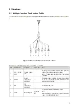
1) Connect the alarm input device to the alarm input port (red or orange) of the I/O cable. 

2) Connect the alarm output device to the alarm output port (brown) and alarm output public port 

(black). The alarm output port supports NO (normal open) alarm device only.  

3) Open the Web, go to the Figure 2-5. Please set the alarm input 01 port for the first channel of the 

I/O cable (red). The alarm input 02 is for the 2

nd

 channel of I/O cable (orange). Then you can select the 

corresponding type (NO/NC.) 

4) Set the WEB alarm output. The alarm output 01 is for the alarm output port of the device. It is the 

No.2 pin of the I/O cable. 


Figure 2-5 Alarm 

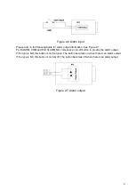
Please refer to the following figure for alarm input information. See Figure 2-6. 

Alarm input: When the input signal is idle or grounded, the device can collect the different statuses of 

the alarm input port. When the input signal is connected to the 5V or is idle, the device collects the 

logic 

“1”. When the input signal is grounded, the device collects the logic “0”. 


Summary of Contents for ICIPB1300VIR

Page 1: ...HD IR Waterproof Fixed Network Camera With Integrated Bracket User s Manual Version 1 0 1...

Page 2: ...r network camera This user s manual is designed to be a reference tool for your system Please read the following safeguard and warnings carefully before you use this series product Please keep this us...

Page 3: ...n Please install the proper power cut off device during the installation connection Always follow the instruction guide the manufacturer recommended 4 Qualified engineers needed All the examination an...

Page 4: ...nclosure when you are installing the device or clean the enclosure when you are doing maintenance work Please use professional optical clean method to clean the enclosure Improper enclosure clean meth...

Page 5: ...Bidirectional talk 6 2 3 1 Device end to PC end 6 2 3 2 PC end to the Device end 6 2 4 Alarm Setup 7 3 Installation 9 3 1 Device Installation 9 3 2 Micro SD Card Installation 9 3 3 Lens Adjustment 10...

Page 6: ...one user belongs to one group The user right shall not exceed the group right Storage Function Support central server backup function in accordance with your configuration and setup in alarm or sched...

Page 7: ...terface Remote operation interface such as WEB DSS PSS System Status Micro SD card status bit stream statistics log and software version Video Parameter Image Sensor 1 3 inch CMOS Pixel 1280 H 960 V D...

Page 8: ...ail function and etc Alarm Input 2 channel input 1 channel output Record and Backup Record Priority Manual External alarm Video detect Schedule Storage Management Support SD card storage NAS storage N...

Page 9: ...on Note 1 DC 12V AC 24V Power input port Power port Input DC 12V AC 24V Please use the provided conversion cable Note Please use according to your actual condition 2 Reset Reset connection optional Ha...

Page 10: ...utput port It is to output the alarm signal to the alarm device NO normal open alarm output port It works with the ALARM_COM port Red ALARM_IN1 Alarm input port 1 It is to receive the on off signal fr...

Page 11: ...port of the PC Login the Web and then click the Audio button to enable the bidirectional talk function You can see the button becomes orange after you enabled the audio talk function Click Audio butto...

Page 12: ...rm input device to the alarm input port red or orange of the I O cable 2 Connect the alarm output device to the alarm output port brown and alarm output public port black The alarm output port support...

Page 13: ...Port ALARM_COM and Port ALARM_NO composes an on off button to provide the alarm output If the type is NO this button is normal open The button becomes on when there is an alarm output If the type is...

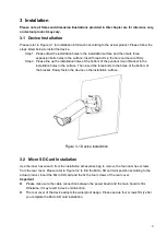
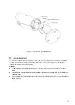
Page 14: ...llation holes in the surface Then insert the three bolts to the holes of the bottom of the bracket Finally fasten the device on the installation surface Figure 3 1 Device installation 3 2 Micro SD Car...

Page 15: ...rod is to zoom See Figure 3 3 Please turn clockwise to fix the lens cover back firmly Important Please remove the sunshield first and remove the lens cover if you can not unfasten the lens cover The l...

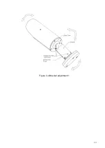
Page 16: ...re 3 5 according to the actual product The horizontal angle of the rear cover can rotate 360 the tilt angle can rotate 90 and the chassis can rotate 360 Please use the inner hex wrench to firmly secur...

Page 17: ...12 Figure 3 4 Bracket adjustment 1...

Page 18: ...D Buttons Please refer to the following contents for detailed information See Figure 3 6 and Figure 3 7 Top button Focus zoom in Bottom button Focus zoon out Left button Far Right button Near Middle b...

Page 19: ...14 Figure 3 6 OSD button 1 Figure 3 7 OSD button 2...

Page 20: ...n as in Figure 4 1 In the device list interface you can view device IP address port number subnet mask default gateway MAC address and etc Figure 4 1 Search interface Select one IP address and then ri...

Page 21: ...o login Please note the port information here shall be identical with the port value you set in TCP port in Web Network interface Otherwise you cannot login the device If you are using device backgrou...

Page 22: ...the PC and the network camera respectively Network camera default IP address is 192 168 1 108 Subnet mask is 255 255 255 0 Gateway is 192 168 1 1 Use order ping network camera address to check connect...

Page 23: ...gin After you successfully logged in please install WEB plug in unit Please refer to the Web Operation Manual included in the resource CD for detailed operation instruction See Figure 5 3 Figure 5 3 W...

Page 24: ...G SanDisk 4G Usually we recommend the 4GB or higher high speed card in case the slow speed results in data loss Audio function Please use active device for the audio monitor input otherwise there is n...

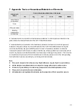
Page 25: ...e toxic or hazardous substance or elements contained in products will not leak or mutate so that the use of these substances or elements will not result in any severe environmental pollution any bodil...

Reviews: