background image


3


Installation  

Dome camera mainly uses ceiling installation; installation surface includes ceiling and wall. 

Users can install the device with the installation position map and the screws in the 

accessories bag.  

Attention:  


Please install the device in time after it is taken apart, which is to avoid the camera 

module being exposed to damp environment for too long.  


Before the installation, please make sure the installation surface is thick enough to sustain 

at least 3X weight of the camera.  
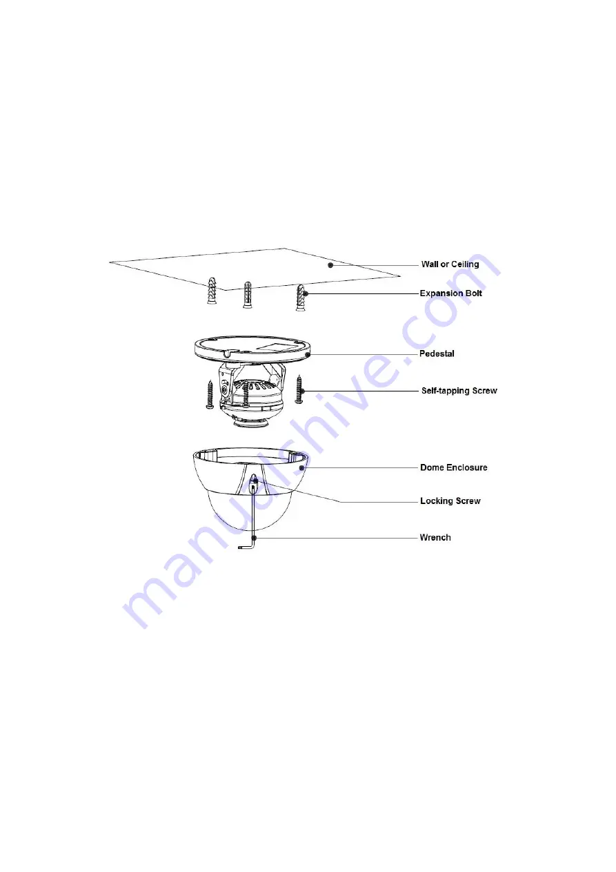


Figure 3-1 

Note:  

The installation figure is for reference only. 


Step 1  

Take out the installation position map from the accessories bag, and paste it on the ceiling or 

wall according to the cable exit location, dig holes on the installation surface according to the 

installation position map, take out the expansion bolts from the accessories bag and insert 

them into the installation holes and fix them.  

Step 2  

Use the wrench to loosen the locking screw in the cover and take down the cover.  

Step 3  

Adjust the location of the dome pedestal according to the top cable outlet or side cable outlet. 

Pull the cable out through the side outlet of installation surface and pedestal (please skip the 

step if it is top cable outlet), aim the screw fixing holes of dome pedestal to the fixing holes of 

Summary of Contents for AVS-4MD4025-IR

Page 1: ...HDAVS Camera User s Manual Version 1 0 0 ...

Page 2: ...i Table of Contents 1 General Introduction 1 1 1 Overview 1 1 2 Features 1 2 Device Framework 2 3 Installation 3 4 Menu 5 4 1 HAVR Settings 5 4 2 Menu Operation 5 Appendix Ⅰ Maintenance 7 ...

Page 3: ... the plug power socket and the junction from the device 2 Environment Please don t aim the device at strong light such as lighting sunlight and so on to focus Please transport use and store the device within the range of allowed humidity and temperature Please do not allow water and other liquid falling into the camera in case that the internal components are damaged Please keep the sound ventilat...

Page 4: ... manual will be regularly upgraded according to the product update the upgraded content will be added in the manual without prior announcement Please contact the customer service for the latest procedure and supplementary documentation The company is not liable for any loss caused by the operation which is not followed by the manual Please refer to the company s final explanation if there is any d...

Page 5: ...xial cable transmission without any loss The distance is over 500m High speed long distance real time transmission Support HDAVS HD video and analog video output Support 3D noise reduction excellent low illuminance performance Support ICR switch to realize surveillance both in the daytime and at night Support OSD menu adjustment parameters Support smart IR function Support WDR DWDR function Suppor...

Page 6: ...2 2 Device Framework See Figure 2 1 for the dimension Figure 2 1 See Figure 2 2 for the cable ports Figure 2 2 ...

Page 7: ... reference only Step 1 Take out the installation position map from the accessories bag and paste it on the ceiling or wall according to the cable exit location dig holes on the installation surface according to the installation position map take out the expansion bolts from the accessories bag and insert them into the installation holes and fix them Step 2 Use the wrench to loosen the locking scre...

Page 8: ...ace Step 4 Connect the video output port of the device cable to the back end HAVR device and connect the power port to power Step 5 Install the dome enclosure install the enclosure which is taken down in step 2 back to the dome pedestal So far you have completed device installation and cable connection you can check device monitoring image via back end coding device ...

Page 9: ...u Setting System PTZ you need to select the channel number for access and set control mode as HDAVS and the protocol as ICR SDI Click Save button to save current setup See Figure 4 1 Figure 4 1 4 2 Menu Operation Click the right mouse button and select PTZ Control then you will see the PTZ Setup menu which is as shown in Figure 4 2 and Figure 4 3 Figure 4 2 ...

Page 10: ...ns zoom and auto trigger focus Note Some of the buttons can only be applied for the motorized vari focal camera Adjust lens focus Auto focus under current zoom rate Lens reset Sheet 4 1 If there is click the Confirm button in Menu Operation interface to go to the 2nd menu Click Return button to go back to the previous menu interface ...

Page 11: ...cloth and wipe several times if it is not clean enough Camera Body Maintenance Use a soft dry cloth to clean the camera body when it is dirty in case the dirt is hard to remove use a clean dry cloth soaked with mild detergent and wipe gently make it dry later Don t use volatile solvent like alcohol benzene thinner and etc or strong detergent with abrasiveness otherwise it will damage the surface c...

Page 12: ...here are subject to change without prior written notice All trademarks and registered trademarks mentioned are the properties of their respective owners If there is any uncertainty or controversy please refer to the final explanation of us Please visit our website or contact your local service engineer for more information ...

Reviews: