


INSTALLATIONS
23
1
+5V
2
Ground
3
Ground
4
+12V
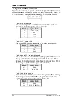
J24: Power Connector, Pitch 2.0mm
Pin #
Signal Name
1
+5V
2
Ground
3
Ground
4
+12V
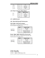
J27: mSATA Socket
CN1, CN3: HDD Serial ATA Connector
CPU_FAN1: CPU Fan Connector
CPU_FAN1 is a 4-pin header for the CPU fan.
The fan must be 12V (Max. 1A).
Pin #
Signal Name
1
Ground
2
+12V
3
Rotation detection
4
Rotation control
FAN1, FAN2, FAN3: System Fan Connectors
FAN1, FAN2, FAN3 is a 4-pin header for system fans.
The fan must be 12V (Max. 1A).
Pin #
Signal Name
1
Ground
2
+12V
3
Rotation detection
4
Rotation control
LED4: Status LED
A1 & C1 : Status LED
A2 & C2 : Bypass or HDD status LED


