4
Instruction Manual IMBus
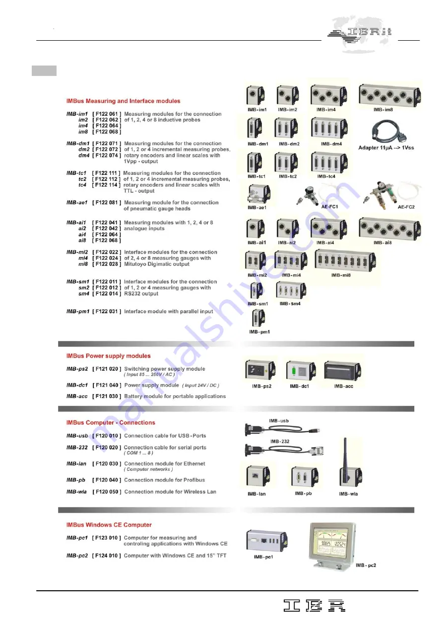
1.3 Overview over the IMBus module types
Page 1: ...M e t r o l o g y Document No D2MF120 000 Edition August 2008 Copyright IBR Messtechnik GmbH Co KG INSTRUCTION MANUAL IMBus IBR Measuring Bus ...
Page 2: ...IMBus measuring and interface modules 8 4 Connection of IMBus to a Computer or to a PLC 4 1 PC Software for configuration and test of IMBus modules 9 4 2 Start up of IMB 232 connection cables 11 4 3 Start up of IMB usb connection cables 12 4 4 Start up of IMB lan connection modules 14 4 5 Start up of IMB wla connection modules 16 4 6 Start up of IMB pb connection modules 18 5 Configuration of IMBu...
Page 3: ...odular structure of 1 to 512 connections and the pos sibility to connect the modules via cables with a maximum length of 1200 m 4000 ft allow an universal use A complete range of software for simple applications up to complex measuring applications with control sequences completes the new IMBus series to an universal tool for measuring data collection analysis and displaying 1 2 Features of IMBus ...
Page 4: ...4 Instruction Manual IMBus 1 3 Overview over the IMBus module types ...
Page 5: ...the same way 2 2 Connection of IMB Connection cable IMB usb IMB 232 1 For fixing the IMB Connection cable replace the two screws by pins The pins are part of the shipment of the IMB Connection cable 2 Secure the IMB Connection cable on the pins by screwing On extended bus systems or on IMB 232 connection cables an IMB power supply module IMB ps2 IMB dc1 IMB acc is required This power supply module...
Page 6: ...the IMB Connection cables or modules The mounting of the bus terminator occurs to the under 2 2 or 2 3 built IMBus systems 1 Replace the screws by pins 2 Plug bus terminator in and screw it fix 2 5 Mounting to DIN rail mount 1 Plug modules on DIN rail mount 2 Pull modules into springs and push modules down The modules are automatically secured on the rail by the springs 2 6 Connection of IMB Exten...
Page 7: ...and foot switches To each IMBus module a separate hand foot switch can be connected Example Addr 7 Addr 6 Addr 5 Addr 4 Addr 3 Addr 2 Addr 1 The hand switch affects the module with Addr 1 Addr 2 The foot switch affects the two modules with Addr 3 to Addr 7 2 8 Connection of gauges and sensors 1 Plug gauge sensor cable in 2 The addresses are automatically assigned in following order starting at the...
Page 8: ...mind the technical specification of the USB port of your device IMB power supply modules IMB ps2 Switching power supply with wide voltage input 85 260 V AC 1200 mA IMB dc1 DC voltage converter for input voltages 9 32 V DC 1200 mA IMB acc Accumulator module for portable units 1200 mA 3 2 Power consumption of IMBus measuring and interface modules IMB im1 20 mA IMB im2 25 mA IMB im4 35 mA IMB im8 45 ...
Page 9: ... necessary Please request design documentation 4 Connection of IMBus to a Computer or to a PLC 4 1 PC Software for configuration and test of IMBus modules 1 Installation For configuration and test of IMBus modules the software IMB_Test is available a Insert the in the delivery included CD into the CD Rom drive b The window for selection of the software is automatically opened Click in the selectio...
Page 10: ...oftware the Setup Button must be pressed Note The Setup window is part of all programmes listed under 9 1 9 6 Note On the IMB usb the Windows device driver must be installed before opening the window see 4 3 Select the PC Connection i e COM 1 USB or IMB lan wlan and after that as IBR instrument the IMBus or as Ser No the serial number of your IMB lan IMB wla connection module After the selection o...
Page 11: ...lay of the state 0 not pressed 1 pressed of the hand foot switches see 2 4 Digital Inputs Display of the state 0 not set 1 set of the digit inputs Digital Outputs By the on off Buttons the digital outputs can be set Mechanical Adjustment Zeroadjustment Calibration are described in chapter 5 1 3 5 1 5 4 2 Start up of IMB 232 connection cables 1 Advantages of RS232 interface COM Port Because the RS2...
Page 12: ... buffer of the COM Port FIFO must be set to 1 otherwise the RS232 interface has a latency time of 400 µsec which reduces the measuring data rate noticeable Æ Call Start Settings Control Panel System Æ Select register card Hardware and press button Device Manager Æ Select the COM Port under Ports COM and LPT Æ Press Button Properties Æ Select Register card Port settings and press Button Advanced Æ ...
Page 13: ...ndow Please insert IBR Support CD Press OK b A new window for inputting the name of the directory with the driver is opened c Press the Button Search A new window for selecting the driver s source directory is opened Select the directory USB Driver on your CD and confirm by clicking on the button Open d By clicking on the OK Button the installation is started 4 Installation of the USB driver under...
Page 14: ...tion of devices in a network Simple connection of IMBus on the usage of Terminal Servers because the mapping of i e COM Ports is not required 2 Electrical connection Connect the IMB lan module to IMBus as described under 2 3 Connect the IMB lan module to network with the correct cable There are two different cables in the shipment Cable with green connectors Î Cross Over Cable for direct connectio...
Page 15: ...ompany network c The IMB lan modules use for the communication 3 different TCP Ports These TCP Ports must be unlocked in the Firewall TCP Port Function 0x2711 10001 Communication with IMBus Modules Measuring data 0x77FE 30718 Detection of connected IMB lan Modules in network 0x77F0 30704 IMBus Control 4 Configuration of IMB lan modules by TelNet Open the Setup Window of IMB_Test programme Selectio...
Page 16: ...en the Setup Window By Telnet the IMB lan module can be configured 4 5 Start up of IMB wla connection modules 1 Advantages of WLAN interface Standard interface for wireless connection of devices in a network Simple connection of IMBus on the usage of Terminal Servers because the mapping of i e COM Ports is not required 2 Electrical connection Connect the IMB wla module to IMBus as described under ...
Page 17: ...of IMB lan wlan as PC Connection and after that selection of the Serial number of the IMB wla module which shall be programmed see 4 4 Press Button Service Press Button Prog IMB lan wlan Telnet By Telnet the programming of the IMB wla modules occurs Telnet Menu Server IP Address IP Address of the IMB wla module 0 0 0 0 Address setting by DHCP Set Gateway IP Address IP Address of the router which s...
Page 18: ...hannel 1 Channel 2 E Mail Expert Security and Factory Defaults These settings must not be changed 5 Short description Configuration of IMB wla modules for network connection by a notebook Set IP Address of Notebook to i e 169 254 100 100 The IMB wla module must be found after power on as W LAN Network LTRX_IBSS on the Notebook Note On the Notebook the usage of Ad hoc networks must be activated Ins...
Page 19: ...s an additional IMB usb IMB 232 cable for the configuration of the IMB measuring modules which are connected to IMB pb module necessary Measuring modules Configuration Profibus Profibus Power supply interface Error LED Connection 4 IMB PB_Setup EXE Configuration Software for IMB pb modules 1 Connect the IMB pb connection module over the configuration interface by 1 to 1 cable in delivery to the CO...
Page 20: ...assigned 19 Bytes data block size to IMB pb module Î The IMB pb module reads continuously from the IMBus Addresses 1 4 the measuring values even if more measuring inputs are available in IMBus and sends the 19 bytes data block to the Profibus Master 5 2 Measuring data block One measuring value data block consists of 4 bytes Byte 1 state information Bit 7 0 Error see bit 6 3 1 Measuring value in By...
Page 21: ...djustment of inductive probes Button Mech Adjust The menu Mech Adj allows the mechanical adjustment of the probes in the fixture The inductive probes contain their smallest linearity error near their mechanical zero point and so the probes must be clamped near their mechanical zero point Insert master into the fixture Insert probe into the fixture and move it in position that the column display of...
Page 22: ...ut After that the software requests to insert the first master and then to insert the second master After collection of the measuring values of both masters the software calculates automatically the gain and offset and stores both values inside the module 5 2 IMB dm1 2 4 1 Short description The IMB dm1 2 4 modules allow the connection of incremental measuring systems with 1Vpp output or together w...
Page 23: ...ncremental measuring systems with TTL output The pining fulfils the Heidenhain Standard 2 Configuration see 5 2 2 5 4 IMB ae1 1 Short description The IMB ae1 modules allow the connection of pneumatic measuring systems 2 Configuration see separate IMB ae1 manual 5 5 IMB ai1 2 4 8 1 Short description The IMB ai1 2 4 8 modules allow the connection of sensors and gauges with analogue output In additio...
Page 24: ...switching modules 6 1 IMB io4 1 Short description The IMBus input and output modules are all galvanically 2kV separated The inputs are compatible to PLC optocoupler inputs and work in a wide voltage area The outputs are ESD proofed short circuit proofed and contain a high driver power Each in output contains a state LED The connections are done by plugable terminal strips 2 Technical data Electric...
Page 25: ...anically 2kV separated The inputs are compatible to PLC optocoupler inputs and work in a wide voltage area Each in output contains a state LED The connections are done by plugable terminal strips 2 Technical data Electrical characteristics Input Nominal input voltage 24 V DC Input voltage signal High 13 V 30 V Input voltage signal Low 30 V 5 V Input current signal High typ 7 mA Connection of 2 wir...
Page 26: ...ts are ESD proofed short circuit proofed and contain a high driver power Each in output contains a state LED The connections are done by plugable terminal strips 2 Technical data Electrical characteristics Output Operating voltage 12 V 32 V DC Max output current 1 A per channel On state resistance RON 200 mΩ Current limitation 4 A 3 Wiring ...
Page 27: ...Module type Module width IMB dm1 IMB tc1 IMB pm1 IMB sm1 25 mm IMB im1 IMB ai1 37 5 mm IMB lan IMB wla IMB im2 IMB dm2 IMB tc2 IMB ae1 IMB ai2 IMB mi2 IMB sm2 50 mm IMB ps2 IMB dc1 IMB io4 IMB ci8 IMB co8 75 mm IMB im4 IMB dm4 IMB tc4 IMB ai4 IMB mi4 IMB sm4 87 5 mm IMB acc IMB pc1 100 mm IMB im8 IMB mi8 IMB ai8 162 5 mm ...
Page 28: ... Measuring modules for connection of incremental measuring systems 1Vpp Supported interfaces 1 Vpp 11 µA by adapter cable Exploitation 200 times Example 0 1 µm on 20 µm period Counter 24 32 Bit for backward counter Measuring rate 1600 Measuring values sec channel Reference mark Failure signal Activatable Deactivatable Operation temperature range 0 45 C Storage temperature range 20 80 C IMB tc1 2 4...
Page 29: ... temperature range 0 45 C Storage temperature range 20 80 C Type of protection IP65 CEI IEC 529 IMB ai1 2 4 8 Measuring modules for connection of analogue voltages and currents Resolution measuring range 16 Bit 10 0 V on 0 5 mV Standard type 2 0 V on 0 1 mV Measuring rate 1800 Measuring values sec channel Operation temperature range 0 45 C Storage temperature range 20 80 C IMB mi2 4 8 Interface mo...
Page 30: ...rature range 0 45 C Storage temperature range 20 80 C IMB ps2 Switching power supply Input voltage 85 260 V AC Frequency range 45 65 Hz Output voltage 5 V Nominal output current IN till 50 C 1 2 A Operation temperature range 0 45 C Storage temperature range 20 80 C IMB dc1 DC voltage converter Input voltage 9 32 V DC Safety extra low voltage Output voltage 5 V Nominal output current IN till 50 C 1...
Page 31: ...ll Speed 12 MBaud Max measuring data rate on 1x IMB im1 500 Measuring values sec Additional function The USB Port can be used for power supply of IMBus modules Operation temperature range 0 45 C Storage temperature range 20 80 C IMB lan Connection module for IMBus to LAN networks Connectable to 10 100 Mbit Ethernet Max measuring data rate on 1x IMB im1 65 Messwerte sec Additional function Support ...
Page 32: ... closing cover Bus terminator Closing Cover IMB wla Connection module for IMBus to Wireless LAN networks IMB wla Connection module Antenna Support CD with drivers IMB_Test Software and manual 4 x pins for fixing the Bus terminator and closing cover Bus terminator Closing Cover IMB pb Connection module for IMBus to Profibus IMB pb Connection module 1 to 1 RS232 Cable for configuration Support CD wi...
Page 33: ... Interface module IMB sm1 2 4 Universal serial interface module IMB sm1 2 4 Interface module IMB pm1 Universal parallel interface module IMB pm1 Interface module IMB ci8 co8 io4 Switching modules IMB ci8 co8 io4 2 x 6 pol plugable terminal strips incl cover IMB ps2 Switching power supply IMB ps2 power supply module 2 x screws Cable for power supply IMB dc1 DC voltage converter IMB dc1 power supply...
Page 34: ... IMBus and any application software It simulates the COM Port on a Windows PC which can be opened by the application software and simu lates the command measuring data format of other multiplexers on the market i e IBRit mc md MUX10 MUX50 Opto RS232 The IBR_VCP software overtakes the communication between IMBus and the application software as a software bridge IBREXDLL Data collection of measuring...
Page 35: ...istical functions the software delivers additional information for the control of production processes Additionally by using ComGage small PLC units can be saved A 30 days Demoversion as well as further information are available under www IBRit com Software packets of other companies The IBR driver is already included in many software packets and so the connection of IMBus to these software packet...
Page 36: ... of delivery This guarantee covers all materials and manufacturing defects Our liability is confined to repair or should we deem it necessary replacing or crediting the goods The following are not covered by the guarantee Damages due to incorrect handling Disregard of operating instructions Tampering by unauthorised staff Attempts by any unauthorised person to repair the instrument In no case any ...