background image

 36

Hardware Maintenance Manual: xSeries 200


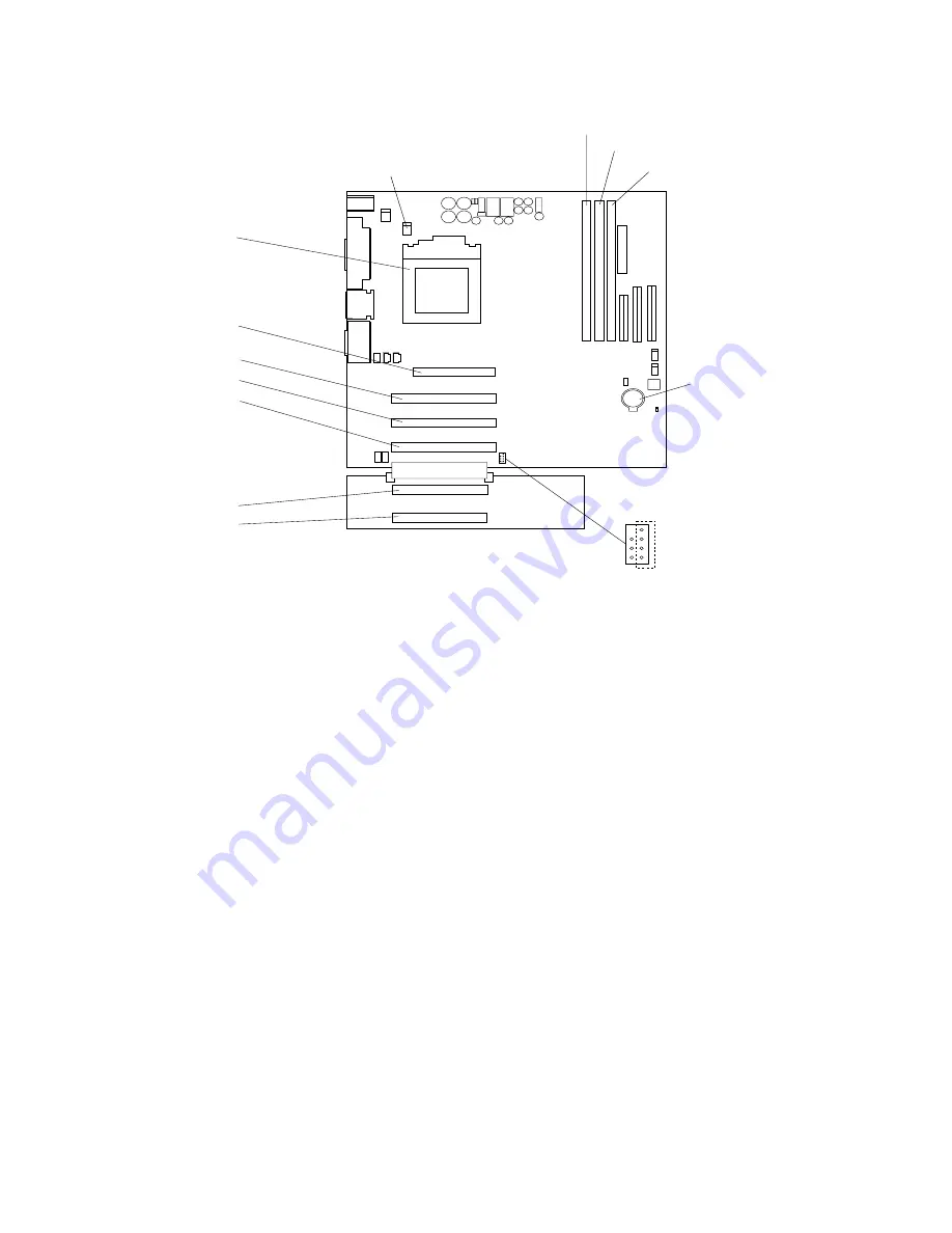
System board internal cable connectors

The following illustration identifies system board connectors for internal cables.

Microprocessor
(U11)

DIMM 1

DIMM 2

DIMM 3

Batter y

PCI 4

PCI 5

PCI 1

PCI 2

PCI 3

AGP
(U15)

Microprocessor

fan sink (CPUFA1)

SCSI LED
(J3)

Summary of Contents for x Series 200

Page 1: ...IBM Hardware Maintenance Manual xSeries 200 ...

Page 2: ......

Page 3: ...IBM Hardware Maintenance Manual xSeries 200 ...

Page 4: ...hanges will be incorporated in new editions of the publication IBM may make improvements and or changes in the product s and or the program s described in this publication at any time This publication was developed for products and services offered in the United States of America IBM may not offer the products services or features discussed in this document in other countries and the information i...

Page 5: ...nual is intended for trained servicers who are familiar with IBM PC Server products Important safety information Be sure to read all caution and danger statements in this book before performing any of the instructions Leia todas as instruções de cuidado e perigo antes de executar qualquer operação Prenez connaissance de toutes les consignes de type Attention et Danger avant de procéder aux opérati...

Page 6: ...gli avvisi di attenzione e di pericolo prima di effettuare qualsiasi operazione Lea atentamente todas las declaraciones de precaución y peligro ante de llevar a cabo cualquier operación Online support Use the World Wide Web WWW to download Diagnostic BIOS Flash Device Driver files and documents The Web address is http www ibm com pc support ...

Page 7: ... 35 System and PCI extender board options connectors 35 System board internal cable connectors 36 System board external connectors 37 System board switches and jumpers 38 Before you begin 38 Working inside the server with the power on 39 System reliability considerations 39 Handling static sensitive devices 39 Moving the stabilizing feet 40 Removing the side cover 40 Removing the bezel 41 Removing...

Page 8: ...No beep symptoms 88 Diagnostic error codes 89 Error symptoms 92 POST error codes 94 Processor board LEDs 99 ServeRAID 100 Undetermined problems 100 Parts listing 101 System 102 Keyboards 103 Power cords 104 Related service information 105 Safety information 105 General safety 105 Electrical safety 106 Safety inspection guide 107 Handling electrostatic discharge sensitive devices 108 Grounding requ...

Page 9: ...e failing system is not part of a shared DASD cluster A system might be part of a cluster if The customer identifies the system as part of a cluster One or more external storage units are attached to the system and at least one of the attached storage units is additionally attached to another system or unidentifiable source One or more systems are located near the failing system If the failing sys...

Page 10: ...ror codes on page 94 Check the System Error Log If an error was recorded by the system see Chapter Symptom to FRU index on page 85 Start the Diagnostic Programs See Diagnostic programs and error messages on page 10 Check for the following responses a One beep b Readable instructions or the Main Menu 3 DID YOU RECEIVE BOTH OF THE CORRECT RESPONSES NO Find the failure symptom in Chapter Symptom to F...

Page 11: ...ge The server serial number and model number are located on labels on the rear and front of the server With access to the World Wide Web up to date information about the server model and other IBM server products is available at the following World Wide Web address http www ibm com pc us eserver xseries Features and specifications The following provides a summary of the features and specifications...

Page 12: ...upply One 330 watt 90 240 V ac Video S3 Savage 4 AGP video adapter Compatible with SVGA and VGA 8 MB SDRAM video memory Size Height 470 mm 18 5 in Depth 508 mm 19 9 in Width 165 mm 6 5 in Weight approximately 19 5 Kg 43 lb when fully configured or 15 9 Kg 35 lb minimum Integrated functions 10BASE T 100BASE TX Ethernet controller on the system board Two serial ports One parallel port Two USB ports ...

Page 13: ...device drivers In addition the ServerGuide CDs include a variety of application programs for the server Note The latest level of BIOS for the server is also available through the World Wide Web Refer to Recovering BIOS on page 14 for the appropriate World Wide Web addresses Reliability availability and serviceability Three of the most important considerations in server design are reliability avail...

Page 14: ...or remote system management Upgradable BIOS diagnostics ASM PCI adapter microcode and POST Wake on LAN WOL capability Microsoft Windows NT failover support Serviceability features 24 7 customer support 3 year warranty parts three 3 years labor one 1 year Adaptec 29160 built in self test BIST Alert on LAN with optional IBM Ethernet adapter CD ROM based diagnostics Diagnostic support of Ethernet ada...

Page 15: ...rver on or off See I O connector locations on page 60 for the location of the input output I O connectors on the rear of the server Turning on the server After you plug one end of the server power cord into the power supply outlet on the rear of the server and the other end of the power cord into an electrical outlet the server can start as follows You can press the power control button on the fro...

Page 16: ...tton for more than four seconds to cause an immediate shutdown of the server and place the server in standby mode You can use this feature if the operating system stops functioning You can disconnect the server power cords from the electrical outlets to shut off all power to the server Note After disconnecting the power cords wait approximately 15 seconds for your system to stop running CAUTION Th...

Page 17: ...rver it performs a series of tests to check the operation of server components and some of the options installed in the server This series of tests is called the power on self test or POST If POST finishes without detecting any problems the first window of the operating system or application program appears Note 1 If you have a power on password or administrator password set you must type the pass...

Page 18: ...grams provide the primary methods of testing the major components of the server Diagnostic error messages indicate that a problem exists they are not intended to be used to identify a failing part Troubleshooting and servicing of complex problems that are indicated by error messages should be performed by trained service personnel SCSI Messages Description All One or more of the following might be...

Page 19: ... the information text message is the diagnostic message that indicates the reason for the problem Text messages The diagnostic text message format is as follows Function Name Result test specific string where Function Name is the name of the function being tested when the error occurred This corresponds to the function code fff given in the previous list Result can be one of the following Passed T...

Page 20: ...7 Select CD ROM as the First Startup Device 8 Press Esc two times to return to the Configuration Setup Utility menu 9 Place the IBM Enhanced Diagnostics CD in the CD ROM drive 10 Select Save Exit Setup and follow the prompts The diagnostics will load Follow the instructions on the screen to run the diagnostics Downloading the diagnostics program Do the following to download the latest image of the...

Page 21: ...Turn on the system and watch the screen If the system is on shut down your operating system and restart the system 3 If a power on password is set the system prompts you for it Type in the appropriate password then press Enter 4 Run the appropriate diagnostics program and when the Diagnostic Programs screen appears select Utility 5 Select View Test Log from the list that appears then follow the in...

Page 22: ...on required for a server to power up see page 100 Recovering BIOS If the BIOS has become corrupted such as from a power failure during a flash update you can recover the BIOS using the boot block jumper and a BIOS flash diskette The boot block jumper selects which of two BIOS images to use In the normal position the jumper will be installed on pins 2 and 3 In the alternate block position the jumpe...

Page 23: ... the peripheral devices 17 Restart the server which should start up normally Clearing CMOS If you need to erase configuration information you must move the CMOS jumper See the illustration in Recovering BIOS on page 14 for the location of the CMOS jumper The default position is a jumper installed on pins 1 and 2 Before you change the position of this jumper you must turn off the server and periphe...

Page 24: ...se of the battery as required by local ordinances or regulations Do the following to replace the battery 1 Read Before you begin on page 38 and follow any special handling and installation instructions supplied with the replacement battery 2 Turn off the server and peripheral devices and disconnect all external cables and power cords then remove the server cover 3 Remove the battery a Use one fing...

Page 25: ... no longer than 30 minutes while the server is operating The processor housing cover covering the processor and memory area is removed for no longer that ten minutes while the server is operating A removed hot swap drive is replaced within two minutes of removal Cables for optional adapters are routed according to the instructions provided with the adapters ensure that cables are not restricting a...

Page 26: ... a crossover cable Note To determine whether a hub has an X port check the port label If the label contains an X the hub has an X port Determine if the hub supports auto negotiation If not try configuring the integrated Ethernet controller manually to match the speed and duplex mode of the hub Check the LAN activity light if available on the front of the server The LAN activity light illuminates w...

Page 27: ...e drivers The network might be idle Try sending data from this workstation Run diagnostics on the LEDs The function of this LED can be changed by device driver load parameters If necessary remove any LED parameter settings when you load the device drivers Data is incorrect or sporadic Check the following Make sure that you are using Category 5 cabling when operating the server at 100 Mbps Make sur...

Page 28: ...lowing Run diagnostics for the Ethernet controller Try a different connector on the hub Reinstall the device drivers Refer to your operating system documentation and to the ServerGuide information If the problem remains call for service Ethernet controller problem Suggested Action Table 3 Ethernet troubleshooting chart ...

Page 29: ...r IntraNetWare system open data link interface ODI Network driver interface specification NDIS adapter for level 4 0 Windows NT Novell NetWare or IntraNetWare system ODI driver teaming messages This section provides explanations of the error messages for the Novell NetWare or IntraNetWare system ODI driver and suggested actions to resolve each problem ...

Page 30: ...ur network supplier Duplicate slot numbers detected Explanation An attempt has been made to bind the same slot number more than once Action Check the slot numbers entered during the bind Adapter slot numbers must be valid and unique If the problem persists contact your network supplier xxx is not supported for AFT team Explanation A bind command has been issued for adapters not supported by AFT NL...

Page 31: ...to reset Check the state of the adapter Explanation The adapter that you specified could not be initialized Action 1 Load the driver for the supported adapter 2 Check that the adapter is seated properly in the slot and try loading the AFT module again If the problem persists contact your network supplier AFT is not supported on this version of NetWare Explanation The NetWare on your server is not ...

Page 32: ...ies gAdvanced 4 Lower the resource values that apply to the transmit queue 0x0E Explanation Could not allocate enough memory for receive queue Action 1 From the Windows NT desktop select Start gControl Panel gNetworks gAdapters 2 Select your IBM Ethernet adapter from the list 3 Select Properties gAdvanced 4 Lower the resource values that apply to the receive queue 0x0F Explanation Could not alloca...

Page 33: ...M xSeries 200 10 100 Ethernet Adapter or the IBM 10 100 Etherjet PCI adapter is enabled 0x17 Explanation Slot parameter not specified in the registry Action Remove the adapter driver and reinstall it If the problem persists call for service All other 4 character hexadecimal codes Action Call for service Error code hex Description Table 5 NDIS Windows NT or Windows 2000 driver messages for the Ethe...

Page 34: ...26 Hardware Maintenance Manual xSeries 200 Ethernet teaming messages This section displays the messages associated with Ethernet teaming ...

Page 35: ...ction None 08 Informational Explanation Team nn Virtual adapter or Team is initialized Action None 09 Informational Explanation Team nn Primary adapter is switching over Action None 10 Warning Explanation Team nn Adapter link down Action Make sure the adapter is functioning properly 11 Informational Explanation Team nn Secondary adapter took over Action None 12 Warning Explanation Team nn Secondar...

Page 36: ...erred primary adapter took over Action None 20 Informational Explanation Team nn Preferred secondary adapter took over Action None 21 Warning Explanation Team nn Primary adapter does not sense any Probes Possible reason partitioned Team Action Make sure the cables of the adapter team are connected to the same LAN segment Reconfigure the team if necessary Event ID Type Description Table 6 NDIS Wind...

Page 37: ...AID configuration program to define and configure the disk array subsystem before you install the operating system ServerGuide CDs The ServerGuide CDs include software setup and installation tools specifically designed for IBM 200 servers You can use these CDs during the initial installation of the server to configure the server hardware and simplify the NOS installation The ServerGuide CDs also c...

Page 38: ...ead only memory EEPROM Devices and I O ports Select this choice to view or change the assignments for devices and input output ports This choice appears only on the full Configuration Setup Utility main menu Start Options Select this choice to view or change the start options Start options take effect when you start the server You can select keyboard operating characteristics such as the keyboard ...

Page 39: ...icroprocessor cache Attention Do not make changes to the Cache Control unless directed to do so by an IBM authorized service representative ROM Shadowing Select this choice to enable or disable the state of a ROM shadowing Chipset Feature Select this choice to modify settings that control features of the core chip set on the system board Attention Do not make changes to the Chipset Feature unless ...

Page 40: ...rt your computer However if you want to change any settings in the Configuration Setup Utility program you must type your administrator password at the password prompt that appears when you try to access the Configuration Setup Utility program If you type your power on password at this prompt you will be able to view limited information in the Configuration Setup Utility program but you will not b...

Page 41: ...iew or change the following controller settings Host Adapter SCSI ID Select this choice to view the SCSI controller identification ID which is usually 7 SCSI Parity Checking Select this choice to view the assigned value of Enabled Host Adapter SCSI Termination Select this choice to view the assigned value of Automatic Boot Device Options Select this choice to configure startable device parameters ...

Page 42: ...e utility program select a drive from the list Read the on screen instructions carefully before making a selection Note If you press Ctrl A before the selected drives are ready an Unexpected SCSI Command Failure screen might appear Restart the server and watch the SCSISelect messages as each drive starts After the drive that you want to view or format starts press Ctrl A ...

Page 43: ... hardware The following illustration shows the major components of the server System and PCI extender board The illustrations in the following sections show the components on the system and PCI extender boards System and PCI extender board options connectors The following illustration identifies system board connectors for options that can be installed Adapter retaining bracket Adapter support bra...

Page 44: ...stem board internal cable connectors The following illustration identifies system board connectors for internal cables Microprocessor U11 DIMM 1 DIMM 2 DIMM 3 Battery PCI 4 PCI 5 PCI 1 PCI 2 PCI 3 AGP U15 Microprocessor fan sink CPUFA1 SCSI LED J3 ...

Page 45: ...ectors for external devices System fan 2 SYSFA2 Support bracket assembly fan SYSFA3 Microprocessor fan sink CPUFA1 Secondary IDE IDE2 Main power JWR1 Front panel connector J1 Diskette drive FDD1 Primary IDE IDE1 SCSI LED J3 Keyboard Mouse Serial A Parallel Serial B Ethernet USB 2 USB 3 MIDI Line out Line in Mic ...

Page 46: ...information about the CMOS jumper Before you begin Before you begin to install options in the server read the following information Become familiar with the safety and handling guidelines provided in Safety information on page 105 Handling electrostatic discharge sensitive devices on page 108 and Safety notices multi lingual translations on page 109 These guidelines will help you work safely while...

Page 47: ...could fall into the server as you lean over it Avoid dropping any metallic objects such as paper clips hair pins or screws into the server System reliability considerations To help ensure proper cooling and system reliability make sure that Each of the drive bays either has a drive or a filler panel and electromagnetic compatibility EMC shield installed There is space around the server to allow th...

Page 48: ...ces indoor humidity and increases static electricity Moving the stabilizing feet The two front feet attached to the bottom of the server rotate 90 degrees to provide additional stability When you need to access the inside of the server to install options you might find it easier to lay the server on its side If you do so rotate the feet in towards the server so they do not break off due to the wei...

Page 49: ...7 mm 1 2 in Then remove the cover from the server 5 Pull out on the cover release tab at the rear of the server then slide the cover toward the front of the server and remove it Attention For proper cooling and airflow replace the cover before turning on the server Operating the server for extended periods of time over 30 minutes with the cover removed might damage server components Removing the b...

Page 50: ...release latch at the top of the server to disconnect the top of the bezel from the server 5 Release the two tabs at the top edge of the bezel and pull the top of the bezel slightly away from the server 6 Pull the bezel up to release the two tabs at the bottom edge of the bezel Store the bezel in a safe place Removing the support bracket assembly When working with some options such as hard disk dri...

Page 51: ... of the support bracket assembly located at the rear of the server 5 Pull the front end of the support bracket assembly away from the server and place the assembly aside To reinstall the support bracket assembly reverse the previous steps Working with adapters Your server comes with adapter connectors called slots The AGP video adapter is installed in the AGP slot You can install up to five PCI ad...

Page 52: ...PCI interrupts PCI expansion slots 1 through 5 are on PCI bus 0 The system scans the AGP slot and PCI expansion slots 1 through 5 to assign system resources then the system starts boots the PCI devices in the following order if you have not changed the default boot sequence PCI expansion slots 1 and 2 system board integrated drive electronics IDE or SCSI devices and then PCI expansion slots 3 thro...

Page 53: ...uctions It might be easier for you to route any cables before you install the adapter 4 If you are installing a full length adapter rotate the front adapter support bracket to the open unlocked position 5 Rotate the rear adapter retaining bracket to the open unlocked position then place it over the rear of the server 6 Remove the PCI expansion slot cover From the rear of the server press in on the...

Page 54: ... If you have another adapter or other options to install do so now 13 If you have installed a full length adapter rotate the front adapter support bracket to the closed locked position 14 Reinstall the rear adapter retaining bracket then rotate the bracket to the closed locked position 15 Reinstall the side cover see Installing the cover on page 59 for details 16 Reconnect the external cables and ...

Page 55: ...er retaining bracket then rotate the bracket to the closed locked position 7 Reinstall the side cover see Installing the cover on page 59 for details 8 Reconnect the external cables and power cords then turn on the peripheral devices and the server Installing internal drives Different types of drives enable your server to read multiple types of media and store data in different formats Depending o...

Page 56: ...options that ship with proper mounting hardware can be supported in the 5 25 in bays 6 If you have a tape backup drive in your server use a dry process cleaning cartridge to clean the tape head two hours after you first use a new data cartridge Then clean the tape head once a month or after each eight hours of continuous read write operations whichever occurs first For complete details about the t...

Page 57: ... are installing a SCSI device be sure to set the SCSI ID for that device Installing a drive in bay 2 or 4 Note The EMI integrity and cooling of the server are both protected by having the bays covered or occupied When you install a drive save the filler panel and EMC shield from the bay in case you later remove the drive and do not replace it with another Complete the following steps to install a ...

Page 58: ...ptical instruments and avoid direct exposure to the beam 5 Touch the static protective bag containing the drive to any unpainted metal surface on the server then remove the drive from the bag and place it on a static protective surface 6 Set any jumpers or switches on the drive according to the documentation that comes with the drive 7 Install the drive If you are installing a 5 25 in drive in bay...

Page 59: ... cables and power cords then turn on the peripheral devices and the server Installing a hard disk drive in bay 5 6 or 7 Complete the following steps to install a hard disk drive in bay 5 6 or 7 Attention When you handle ESD sensitive devices take precautions to avoid damage from static electricity see Handling static sensitive devices on page 39 1 Read the information in Preinstallation steps all ...

Page 60: ...pport bracket assembly on page 42 and System board internal cable connectors on page 36 for the location of the fan cable connector 12 Reinstall the side cover see Installing the cover on page 59 for details 13 Reconnect the external cables and power cords then turn on the peripheral devices and the server Installing memory modules Adding memory to your server is an easy way to make programs run f...

Page 61: ...cket assembly and disconnect the fan cable from the connector SYSFA3 on the system board See Removing the support bracket assembly on page 42 and System board internal cable connectors on page 36 for the location of the fan cable connector 4 Touch the static protective package containing the DIMM to any unpainted metal surface on the server Then remove the DIMM from the package 5 Install the DIMM ...

Page 62: ...r the location of the fan cable connector 8 Replace the side cover see Installing the cover on page 59 9 Reconnect the external cables and power cords and turn on the peripheral devices and the server If you want to remove a DIMM reverse the previous steps Removing and installing a microprocessor The server only supports one microprocessor which is installed on the system board in the microprocess...

Page 63: ...e connector SYSFA3 on the system board See Removing the support bracket assembly on page 42 and System board internal cable connectors on page 36 for the location of the fan cable connector 4 Push down and back on the heat sink retainer to remove it from the heat sink 5 Firmly grasp the heat sink and lift it off the microprocessor Note Once you remove the heat sink from the microprocessor you must...

Page 64: ...instructions 4 Install the microprocessor a Touch the static protective package containing the new microprocessor to any unpainted metal surface on the server then remove the microprocessor from the package b Pull out and lift up on the microprocessor release lever to unlock the microprocessor connector c Orient the microprocessor over the microprocessor connector as shown in the following illustr...

Page 65: ...n top of the microprocessor c Align and push the fan sink retainer through the groove in the center of the fan sink d Insert a small flat bladed screwdriver into the tab on the fan sink retainer e Press the screwdriver down to snap the fan sink retainer into place f Connect the fan sink power cable to the microprocessor fan sink connector CPUFA1 on the system board See System board internal cable ...

Page 66: ...stall a U bolt 1 Review the safety precautions listed in Safety information on page 105 2 Turn off the server and peripheral devices and disconnect all external cables and power cords then remove the cover see Removing the side cover on page 40 for details 3 Use a screwdriver to remove the two metal knockouts 4 Insert the U bolt through the rear panel then attach and tighten the nuts 5 If you have...

Page 67: ...ion Note If you have just plugged the power cords of the server into an electrical outlet you will have to wait approximately 20 seconds before pressing the power control button Installing the cover The following illustration shows how install the server side cover Note The illustrations in this document might differ slightly from your hardware Note If you removed the support bracket assembly afte...

Page 68: ...tion that comes with your option for information about installing any required device drivers If the server has a ServeRAID adapter installed and you have installed or removed a hard disk drive refer to the documentation that comes with your ServeRAID adapter for information about reconfiguring your disk arrays Connecting external options You can attach a SCSI storage expansion enclosure to the se...

Page 69: ...the location of the PCI slots Input output ports This section provides information about the I O ports on your server These ports include the following One mouse port One keyboard port One parallel port Two serial ports One Ethernet port Two USB ports Line out Line in Mic MIDI One video port One Ultra 3 160 SCSI port some models Power cord connector Mouse Keyboard Parallel Serial A Serial B USB 3 ...

Page 70: ...ur server see I O connector locations on page 60 for its location Note If you attach a standard non USB keyboard to the keyboard connector the USB ports and devices will be disabled during the power on self test Table 7 Mouse connector pin number assignments Pin Signal 1 Data 2 Not connected 3 Ground 4 5 V dc 5 Clock 6 Not connected Table 8 Keyboard connector pin number assignments Pin I O Signal ...

Page 71: ...Restart the server and watch the monitor screen 2 When the message Press F1 for Configuration Setup appears press F1 3 When the Configuration Setup Utility menu appears select Devices I O Ports then press Enter 4 Select the parallel connector then use the arrow keys to advance through the settings available Note When you configure the parallel connector as bidirectional use an IEEE 1284 compliant ...

Page 72: ...view or change the serial connector assignments 1 Restart the server and watch the monitor screen 2 When the message Press F1 for Configuration Setup appears press F1 Table 9 Parallel connector pin number assignments Pin I O SPP ECP Signal EPP Signal 1 O STROBE WRITE 2 I O Data 0 Data 0 3 I O Data 1 Data 1 4 I O Data 2 Data 2 5 I O Data 3 Data 3 6 I O Data 4 Data 4 7 I O Data 5 Data 5 8 I O Data 6...

Page 73: ...st Ethernet standard requires that the cabling in the network be Category 5 Configuring the Ethernet controller When you connect your server to the network the Ethernet controller automatically detects the data transfer rate 10Mbps or 100Mbps on the network and then sets the controller to operate at the appropriate rate In addition if the Ethernet connector that your server is connected to support...

Page 74: ...You can only use FEC with a switch that has FEC capability Teaming requires you to install at least one additional Ethernet adapter For additional information about the teaming modes refer to the documentation that comes with these additional adapters Priority Packet Mode Priority Packet is a traffic prioritization utility that enables you to set up filters to process high priority traffic before ...

Page 75: ...ovide the precise priority levels of 802 1p tagging it does assign traffic as either high or low priority and sends high priority packets first Therefore if there are multiple applications on a system sending packets the packets from the application with a filter are sent out first HPQ does not change network routing nor does it add any information to the packets To assign HPQ you can specify it u...

Page 76: ...he server to join The VLANs you add are listed on the Adapters tab 7 Select Close and restart the computer Ethernet connector There is an RJ 45 Ethernet connector on the back of the server see I O connector locations on page 60 for the location of this connector The following table shows the pin number assignments for the Ethernet connector Universal Serial Bus connectors Your server has two Unive...

Page 77: ...e location of these connectors Line out This connector is used to send audio signals from the server to external devices such as powered speakers with built in amplifiers headphones multimedia keyboards or the audio Line in connector on a stereo system Line in This connector is used to accept audio signals from external devices such as line output from a stereo television or musical instrument int...

Page 78: ...ackage This configuration supports a zero wait state 32 bit memory transfers at 160 Mbytes second when LVD SCSI peripherals are attached This channel supports up to 15 SCSI devices In addition this adapter uses Double transition clocking to achieve high transfer rates Table 13 MIDI connector pin number assignments Pin Signal Pin Signal Pin Signal 1 5 V 6 Joystick 1 Y 11 Joystick 2 X 2 Joystick 1 S...

Page 79: ...system board See System and PCI extender board options connectors on page 35 for the location of the SCSI connector For information about the maximum length of a SCSI cable between the terminated ends of the cable refer to the American National Standards Institute ANSI SCSI standards Adhering to these standards will help ensure that your server operates correctly Setting SCSI IDs Each SCSI device ...

Page 80: ...5 Data 5 12 Data 6 46 Data 6 13 Data 7 47 Data 7 14 Data P 48 Data P 15 Ground 49 Ground 16 DIFFSENS 50 Ground 17 Term power 51 Term power 18 Term power 52 Term power 19 Reserved 53 Reserved 20 Ground 54 Ground 21 Attention 55 Attention 22 Ground 56 Ground 23 Busy 57 Busy 24 Acknowledge 58 Acknowledge 25 Reset 59 Reset 26 Message 60 Message 27 Select 61 Select 28 Control Data 62 Control Data 29 Re...

Page 81: ...l on page 41 4 Remove the cover see Removing the side cover on page 40 5 Remove the support bracket see Removing the support bracket assembly on page 42 6 Remove any hard disk drives or drive fillers from the drives 7 Disconnect the hard disk drive cables from the system board 8 Remove the screws from the front of the hard disk drive cage 9 Move the cage slightly in and up until it is free of the ...

Page 82: ...ve the cover see Removing the side cover on page 40 4 Disconnect the power cables from the system board 5 Remove the screws from the rear of the server 6 Gently move the power supply away from the chassis and lift it out of the server Rear fan Before you begin Read Safety information on page 105 Review the information in Before you begin on page 38 ...

Page 83: ...away from the server and lift it up and out 8 To install the new fan assembly place the fan in position at the rear of the server 9 Guide the rubber extensions through the apertures 10 Use needle nosed pliers to pull the extensions through the apertures 11 Reconnect cables System board Before you begin Read Safety information on page 105 Review the information in Before you begin on page 38 Note I...

Page 84: ...onnect the cables 7 Remove the adapter cards and both adapter retaining brackets see Installing an adapter on page 45 8 Remove the hot swap hard disk drive cage see Hard disk drive cage on page 73 9 Remove memory modules see Installing memory modules on page 52 10 Remove microprocessors and or terminator cards see Removing and installing a microprocessor on page 54 11 Remove screws and lift the sy...

Page 85: ...rive cage 6 Gently slide the CD ROM drive toward the front of the server and lift it out Floppy disk drive Before you begin Read Safety information on page 105 Review the information in Before you begin on page 38 To remove the floppy disk drive do the following 1 Power off the server if it is on 2 Unplug the server 3 Remove the cover see Removing the side cover on page 40 4 Disconnect the cables ...

Page 86: ...n page 40 4 Remove the front bezel see Removing the bezel on page 41 5 Remove the hot swap hard disk drive see Hard disk drive cage on page 73 6 Disconnect the cable of the button kit from the system board 7 Place a screwdriver against the bottom release latch of the button kit and gently press upward and slide the latch through the aperture 8 Gently pinch together the upper release latches and sl...

Page 87: ...emove the support bracket see Removing the support bracket assembly on page 42 6 Remove all adapter cards 7 Unplug the speaker from the system board 8 Gently push the two tabs of the adapter guide assembly inward until the assembly is released lift it up and out of the server 9 Slide the speaker up and out of the server Bezel release latch Before you begin Read Safety information on page 105 Revie...

Page 88: ... the front bezel see Removing the bezel on page 41 5 Remove the handle assembly see Handle assembly on page 81 6 Remove the top side cover see Top side cover 7 Press down on the tab 8 From the underside grasp the bezel release latch in the center and gently pull it back and away from the server Top side cover Before you begin Read Safety information on page 105 Review the information in Before you...

Page 89: ... bezel see Removing the bezel on page 41 5 Remove the handle assembly see Handle assembly 6 Remove the four screws from the back of the server and put them in a safe place 7 Using a screwdriver gently pry the cover away from the server in the rear and slide the unit away from the server Handle assembly Before you begin Read Safety information on page 105 Review the information in Before you begin ...

Page 90: ...dle 4 Lift up on the handle cap to separate it from the handle support To remove the handle support do the following 1 Power off the server if it is on 2 Unplug the server 3 Firmly grasp the handle support and slide it away from the front bezel 4 Lift up on the handle support to remove it from the slots in the top of the chassis Adapter retainer Before you begin Read Safety information on page 105...

Page 91: ...erver if it is on 2 Unplug the server 3 Remove the cover see Removing the side cover on page 40 4 Remove all adapter cards see Installing an adapter on page 45 5 Rotate the adapter retainer to the open position 6 Grasp the adapter retainer and gently slide the top and bottom tabs out of the notches ...

Page 92: ...84 Hardware Maintenance Manual xSeries 200 ...

Page 93: ...FRU lists symptoms errors and the possible causes The most likely cause is listed first Use this Symptom to FRU index to help you decide which FRUs to have available when servicing the computer The POST BIOS displays POST error codes and messages on the screen Beep symptoms Beep symptoms are short tones or a series of short tones separated by pauses intervals without sound See the following exampl...

Page 94: ...ssor 3 System Board 1 4 3 Interrupt vector loading test failed 1 System Board 2 1 1 Secondary DMA register failed 1 System Board 2 1 2 Primary DMA register failed 1 System Board 2 1 3 Primary interrupt mask register failed 1 System Board 2 1 4 Secondary interrupt mask register failed 1 System Board 2 2 1 Interrupt vector loading failed 1 System Board 2 2 2 Keyboard controller failed 1 System Board...

Page 95: ...n believed operable 1 System board 3 1 1 Timer tick interrupt failed 1 System Board 3 1 2 Interval timer channel 2 failed 1 System Board 3 1 3 RAM test failed above address OFFFFH 1 DIMM 2 Memory card 3 System board 3 1 4 Time of Day clock failed 1 Battery 2 System Board 3 2 1 Serial port failed 1 System board 3 2 2 Parallel port failed 1 System board 3 2 3 Math coprocessor failed 1 Processor 2 Sy...

Page 96: ...2 DIMMs 3 System Board Two Short Beeps Information only the configuration has changed 1 Run Diagnostics 2 Run Configuration Setup Three Short Beeps 1 DIMM 2 System Board One Continuous Beep 1 Processor 2 System Board Repeating Short Beeps 1 Keyboard 2 System Board One Long and One Short Beep 1 Video adapter if present 2 System Board One Long and Two Short Beeps 1 Video adapter if present 2 System ...

Page 97: ...de Symptom FRU Action 001 XXX 000 Failed core tests 1 System Board 001 XXX 001 Failed core tests 1 System Board 001 250 000 Failed System Board ECC 1 System Board 001 250 001 Failed System Board ECC 1 System Board 005 XXX 000 Failed Video test 1 Video Adapter if installed 2 System Board 011 XXX 000 Failed COM1 Serial Port test 1 System Board 011 XXX 001 Failed COM2 Serial Port test 1 System Board ...

Page 98: ...g a FRU 1 Adapter 2 SCSI Backplane 3 Cable 035 XXX SNN Check System Error Log before replacing a FRU S number of failing PCI slot NN SCSI ID of failing fixed disk 1 Fixed Disk with SCSI ID NN on RAID adapter in PCI slot S 035 253 S99 RAID adapter initialization failure 1 ServeRAID Adapter in slot S is not configured properly Obtain the basic and extended configuration status and refer to the Serve...

Page 99: ...ical array 1 Fixed Disk 2 217 XXX 002 Failed BIOS Fixed Disk test Note If RAID is configured the fixed disk number refers to the RAID logical array 1 Fixed Disk 3 264 XXX 0NN NN SCSI ID of failing Tape Drive 1 Tape Cartridge if user executed the Read Write Tape Drive test XXX 256 2 SCSI or power cable connected to the tape drive with SCSI ID NN 3 Tape drive with SCSI ID NN refer to Help and Servic...

Page 100: ... CD 2 Run CD ROM diagnostics 3 CD ROM Drive CD ROM drive tray is not working The server must be powered on 1 Insert the end of a paper clip into the manual tray release opening 2 Run CD ROM diagnostics 3 CD ROM Drive CD ROM drive is not recognized 1 Run Configuration Setup enable primary IDE channel 2 Check cables and jumpers 3 Check for correct device driver 4 Run CD ROM diagnostics 5 CD ROM driv...

Page 101: ...Error and DIMM X LED on 1 Replace DIMM X System Error and CPU X LED on 1 Replace CPU X Setup Action Setup and Installation CD won t start Be sure the server is supported all eServers with a startable bootable CD ROM drive are supported If the startup boot sequence settings have been altered be sure the CD ROM is first in the boot sequence If more than one CD ROM drive is installed be sure that onl...

Page 102: ... your NOS CD Be sure the NOS CD you have is supported by ServerGuide See the Setup and Installation CD label for a list of NOS versions supported Can t install NOS option is grayed out Either there is no logical drive defined ServeRAID systems or the ServerGuide system partition is not present Run the setup and configuration program TechConnect CD Action Can t start TechConnect CD Be sure you re s...

Page 103: ...onfiguration Setup 2 Battery 3 Failing Device 4 System Board 163 Real Time Clock error 1 Run Configuration Setup 2 Battery 3 System Board 164 Memory configuration changed see Memory Settings on page 31 1 Run Configuration Setup 2 DIMM 3 System Board 175 Hardware error 1 System Board 176 177 178 Security hardware error 1 Run Configuration Setup 2 System Board 184 Power on password corrupted 1 Run C...

Page 104: ... Run memory diagnostics 2 DIMM 3 System Board 229 Cache error 1 Microprocessor 289 DIMM has been disabled by user or system see Memory Settings on page 31 1 Run Configuration Setup if disabled by user 2 Disabled DIMM if not disabled by user 301 Keyboard or keyboard controller error 1 Keyboard 2 System Board 303 Keyboard controller error 1 System Board 2 Keyboard 602 Invalid diskette boot record 1 ...

Page 105: ...er 3 System Board 1962 Drive does not contain a valid boot sector 1 Verify a bootable operating system is installed 2 If RAID system refer to the Hardware Maintenance Manual for the specific RAID adapter 3 Run Diagnostics 4 Hard Disk Drive 5 Cable 6 SCSI Backplane 7 System Board 2400 Video controller test failure 1 Video Adapter if installed 2 System Board 2462 Video memory configuration error 1 V...

Page 106: ...ry below 1MB for PCI adapter 1 Run Configuration Setup 2 Failing Adapter 3 System Board 00180500 PCI option ROM checksum error 1 Remove Failing PCI Card 2 System Board 00180600 PCI device built in self test failure 1 Run Configuration Setup 2 Failing Adapter 3 System Board 00180700 xxxxyyyy planar PCI device not responding where xxxx is PCI vendor ID and yyyy is PCI device ID 1 System Board 2 PCI ...

Page 107: ...Check cable 2 Check for interruption of power supply 3 Power Cable Other numbers Follow instructions on screen Table 16 LED Cause Fan 1 Replace the fan assembly Memory 1 Replace the DIMM indicated by the lit DIMM error CPU 1 If a microprocessor LED is on for a microprocessor connector that has a terminator card installed instead of a microprocessor the microprocessors are not installed in the corr...

Page 108: ...and reconfigure each time Any external devices Surge suppressor device on the computer Modem printer mouse or non IBM devices Each adapter Drives Memory Modules Minimum requirement one 128 MB DIMM Note Minimum operating requirements are a 1 Power Supply b System Board c 1 Microprocessor d 1 Terminator Card in Slot 2 e 1 Memory Module minimum of 1 DIMM in slot labeled DIMM 1 4 Power on the computer...

Page 109: ... Copyright IBM Corp 2000 101 Parts listing 14 1 2 3 4 5 6 7 8 9 10 11 12 13 15 16 17 18 19 20 21 22 23 24 25 26 29 27 28 29 30 31 ...

Page 110: ...els 23X 33X 62X 72X 19K1485 19 15 GB IDE hard file 7K RPM Models 11X 12X 41X 51X 61X 71X 19K1564 19 20 0 GB ATA 100 IDE HDD Models 21X 22X 31X 61X 71X 19K1565 20 Door assembly sliding w lock latch All models 06P5854 21 PCI extender card All models 22P9768 22 Memory 64MB ECC 133MHz SDRAM Models 10X 11X 12X 20X 21X 22X 31X 40X 41X 50X 51X 61X 71X only 33L3080 22 Memory 128MB ECC 133MHz SDRAM Models ...

Page 111: ...215 10 20Gb TR5 IDE tape driver Model 12X 22X only 37L5805 S3 Video NVAGP4 8MB All models 10K2940 Bezel kit All models 00N7082 Cable SCSI 5 drop Models 10X 13X 40X 42X 50X 52X only 00N7110 Cable IDE 2 drop All models 09N5925 Cable floppy disk drive All models 76H4228 Cable SCSI LED Models 10X 13X 40X 42X 50X 52X only 76H7344 Cable CD ROM audio All models 75H9219 Power cord All models 6952301 Keybo...

Page 112: ...nzania Uganda United Kingdom Yemen Zambia 12J5987 Afghanistan Algeria Andorra Angola Austria Belgium Benin Bulgaria Burkina Faso Burundi Cameroon Central African Rep Chad Czech Republic Egypt Finland France French Guiana Germany Greece Guinea Hungary Iceland Indonesia Iran Ivory Coast Jordan Lebanon Luxembourg Macau Malagasy Mali Martinique Mauritania Mauritius Monaco Morocco Mozambique Netherland...

Page 113: ...hat you think are too heavy for you Do not perform any action that causes hazards to the customer or that makes the equipment unsafe Before you start the machine ensure that other service representatives and the customer s personnel are not in a hazardous position Place removed covers and other parts in a safe place away from all personnel while you are servicing the machine Keep your tool case aw...

Page 114: ...erate the switch or unplug the power cord quickly Do not work alone under hazardous conditions or near equipment that has hazardous voltages Disconnect all power before Performing a mechanical inspection Working near power supplies Removing or installing main units Before you start to work on the machine unplug the power cord If you cannot unplug it ask the customer to power off the wall box that ...

Page 115: ...dent occurs Use caution do not become a victim yourself Switch off power Send another person to get medical aid Safety inspection guide The intent of this inspection guide is to assist you in identifying potentially unsafe conditions on these products Each machine as it was designed and built had required safety items installed to protect users and service personnel from injury This guide addresse...

Page 116: ...hine the part the work mat and the person handling the part are all at the same charge Notes 1 Use product specific ESD procedures when they exceed the requirements noted here 2 Make sure that the ESD protective devices you use have been certified ISO 9000 as fully effective When handling ESD sensitive parts Keep the parts in protective packages until they are inserted into the product Avoid conta...

Page 117: ...r 1 translations for that caution statement appear in this section under statement 1 Be sure to read all caution and danger statements before performing any of the instructions Statement 1 DANGER Electrical current from power telephone and communication cables is hazardous To avoid a shock hazard Do not connect or disconnect any cables or perform installation maintenance or reconfiguration of this...

Page 118: ... local ordinances or regulations Statement 3 CAUTION When laser products such as CD ROMs DVD ROM drives fiber optic devices or transmitters are installed note the following Do not remove the covers Removing the covers of the laser product could result in exposure to hazardous laser radiation There are no serviceable parts inside the device Use of controls or adjustments or performance of procedure...

Page 119: ...ntrol button on the device and the power switch on the power supply do not turn off the electrical current supplied to the device The device also might have more than one power cord To remove all electrical current from the device ensure that all power cords are disconnected from the power source Statement 10 CAUTION Do not place any object weighing more than 82 kg 180 lbs on top of rack mounted d...

Page 120: ...ntação a tomadas elétricas corretamente instaladas e aterradas Conecte todos os equipamentos ao qual esse produto será conectado a tomadas corretamente instaladas Sempre que possível utilize apenas uma das mãos para conectar ou desconectar cabos de sinal Nunca ligue qualquer equipamento quando existir evidência de danos por fogo água ou na estrutura Desconecte cabos de alimentação sistemas de tele...

Page 121: ...informações sobre como enviar a bateria pelo correio para a IBM Instrução 3 PRECAUCIÓN Quando produtos a laser unidades de CD ROM unidades de DVD dispositivos de fibra ítica transmissores etc estiverem instalados observe o seguinte Não remova as tampas A remoção das tampas de um produto a laser pode resultar em exposição prejudicial à radiação de laser Nenhuma peça localizada no interior do dispos...

Page 122: ... elétrica fornecida ao dispositivo O dispositivo também pode ter mais de um cabo de alimentação Para remover toda a corrente elétrica do dispositivo assegure que todos os cabos de alimentação estejam desconectados da fonte de energia elétrica CUIDADO Instrução 10 CUIDADO Não coloque nenhum objeto com peso superior a 82 kg 180 lbs sobre dispositivos montados em rack 18 kg 37 lbs 32 kg 70 5 lbs 55 k...

Page 123: ...Related service information 115 ...

Page 124: ...116 Hardware Maintenance Manual xSeries 200 ...

Page 125: ...Related service information 117 ...

Page 126: ...118 Hardware Maintenance Manual xSeries 200 ...

Page 127: ...Related service information 119 ...

Page 128: ...120 Hardware Maintenance Manual xSeries 200 ...

Page 129: ...Related service information 121 ...

Page 130: ...122 Hardware Maintenance Manual xSeries 200 ...

Page 131: ...installation d entretien ou de reconfiguration de ce produit au cours d un orage Branchez tous les cordons d alimentation sur un socle de prise de courant correctement câblé et mis à la terre Branchez sur des socles de prise de courant correctement câblés tout équipement connecté à ce produit Lorsque cela est possible n utilisez qu une seule main pour connecter ou déconnecter les câbles d interfac...

Page 132: ...sont installés tels que des unités de CD ROM ou de DVD des périphériques contenant des fibres optiques ou des émetteurs récepteurs prenez connaissance des informations suivantes N ouvrez pas ces produits pour éviter une exposition directe au rayon laser Vous ne pouvez effectuer aucune opération de maintenance à l intérieur Pour éviter tout risque d exposition au rayon laser respectez les consignes...

Page 133: ...cte au rayon Notice n 4 ATTENTION Faites vous aider pour soulever ce produit Notice n 5 ATTENTION Le bouton de mise sous tension hors tension de l unité et l interrupteur d alimentation du bloc d alimentation ne coupent pas l arrivée de courant électrique à l intérieur de la machine Il se peut que votre unité dispose de plusieurs cordons d alimentation Pour isoler totalement l unité du réseau élec...

Page 134: ...126 Hardware Maintenance Manual xSeries 200 ATTENTION Ne posez pas d objet dont le poids dépasse 82 kg sur les unités montées en armoire ...

Page 135: ...senen Geräte ebenfalls an Schutzkontaktsteckdosen mit ordnungsgemäß geerdetem Schutzkontakt anschließen Signalkabel möglichst einhändig anschließen oder lösen Keine Geräte einschalten wenn die Gefahr einer Beschädigung durch Feuer Wasser oder andere Einflüsse besteht Die Verbindung zu den angeschlossenen Netzkabeln Telekommunikationssystemen Netzwerken und Modems ist vor dem öffnen des Gehäuses zu...

Page 136: ...odukt z B CD ROM Laufwerke DVD Laufwerke Einheiten mit Glasfaserkabeln oder Transmitter installiert ist beachten Sie folgendes Das Entfernen der Abdeckungen des CD ROM Laufwerks kann zu gefährlicher Laserstrahlung führen Es befinden sich keine Teile innerhalb des CD ROM Laufwerks die vom Benutzer gewartet werden müssen Die Verkleidung des CD ROM Laufwerks nicht öffnen Steuer und Einstellelemente s...

Page 137: ... Betriebsspannungsschalter am Netzteil wird die Stromversorgung für den Server nicht unterbrochen Der Server könnte auch mehr als ein Netzkabel aufweisen Um die gesamte Stromversorgung des Servers auszuschalten muß sichergestellt werden daß alle Netzkabel aus den Netzsteckdosen herausgezogen wurden Hinweis 10 ACHTUNG Keine Gegenstände die mehr als 82 kg wiegen auf Rack Einheiten ablegen 18 kg 32 k...

Page 138: ...ta e munita di terra di sicurezza Collegare qualsiasi apparecchiatura collegata a questo prodotto ad una presa elettrica correttamente cablata e munita di terra di sicurezza Quando possibile collegare o scollegare i cavi di segnale con una sola mano Non accendere qualsiasi apparecchiatura in presenza di fuoco acqua o se sono presenti danni all apparecchiatura stessa Scollegare i cavi di alimentazi...

Page 139: ...22 del 5 2 9 e successive disposizioni nazionali e locali Avviso 3 ATTENZIONE Quando si installano prodotti laser come ad esempio le unità DVD CD ROM a fibre ottiche o trasmettitori prestare attenzione a quanto segue Non rimuovere i coperchi L apertura dei coperchi di prodotti laser può determinare l esposizione a radiazioni laser pericolose All interno delle unità non vi sono parti su cui effettu...

Page 140: ...alimentazione posto sull alimentatore non disattiva la corrente elettrica fornita all unità L unità potrebbe disporre di più di un cavo di alimentazione Per disattivare la corrente elettrica dall unità accertarsi che tutti i cavi di alimentazione siano scollegati dalla sorgente di alimentazione Avviso 10 ATTENZIONE Non poggiare oggetti che pesano più di 82 kg sulla parte superiore delle unità mont...

Page 141: ...Related service information 133 ...

Page 142: ...134 Hardware Maintenance Manual xSeries 200 ...

Page 143: ...Related service information 135 ...

Page 144: ...cte ningún cable ni realice las operaciones de instalaciín mantenimiento o reconfiguraciín de este producto durante una tormenta Conecte cada cable de alimentaciín a una toma de alimentaciín eléctrica con conexiín a tierra y cableado correctos Conecte a tomas de alimentaciín con un cableado correcto cualquier equipo que vaya a estar conectado a este producto Si es posible utilice una sola mano cua...

Page 145: ... Declaración 3 PRECAUCIÓN Cuando instale productos láser como por ejemplo CD ROM unidades DVD dispositivos de fibra íptica o transmisores tenga en cuenta las advertencias siguientes No retire las cubiertas Si retira las cubiertas del producto láser puede quedar expuesto a radiaciín láser perjudicial Dentro del dispositivo no existe ninguna pieza que requiera mantenimiento El uso de controles o aju...

Page 146: ...ación 4 PRECAUCIÓN Tome medidas de seguridad al levantar el producto Declaración 5 PRECAUCIÓN El botín de control de alimentaciín del dispositivo y el interruptor de alimentaciín de la fuente de alimentaciín no apagan la corriente eléctrica suministrada al dispositivo Es posible también que el dispositivo tenga más de un cable de alimentaciín Para eliminar la corriente eléctrica del dispositivo as...

Page 147: ...Related service information 139 PRECAUCIÓN No coloque ningún objeto que pese más de 82 kg 180 libras encima de los dispositivos montados en bastidor ...

Page 148: ...nk you for your response 1 Do you like this manual Yes No _________________________________________ _________________________________________ 2 What would you like to see added changed or deleted in this manual _________________________________________ _________________________________________ 3 What is your service experience level Less than five years More than five years 4 Which servers do you ...

Page 149: ...Have the same BIOS level 3 Have the same adapters attachments in the same locations 4 Have the same address jumpers terminators cabling 5 Have the same software versions and levels 6 Have the same Reference Diagnostics Diskette version 7 Have the same configuration options set in the system 8 Have the same setup for the operation system control files Comparing the configuration and software set up...

Page 150: ...imited to the implied warranties of merchantability and fitness for particular purpose These products are offered and warranted solely by third parties Trademarks The following items are trademarks of the IBM Corporation in the United States or other countries or both The following terms are trademarks of other companies Lotus and Lotus Notes are trademarks of Lotus Development Corporation Intel P...

Page 151: ......

Page 152: ...IBM Part Number 06P8517 Printed in the United States of America on recycled paper containing 10 recovered post consumer fiber 06P8517 0406P8517 ...

Reviews: