background image

7-26

TS3400 Tape Library Maintenance Information

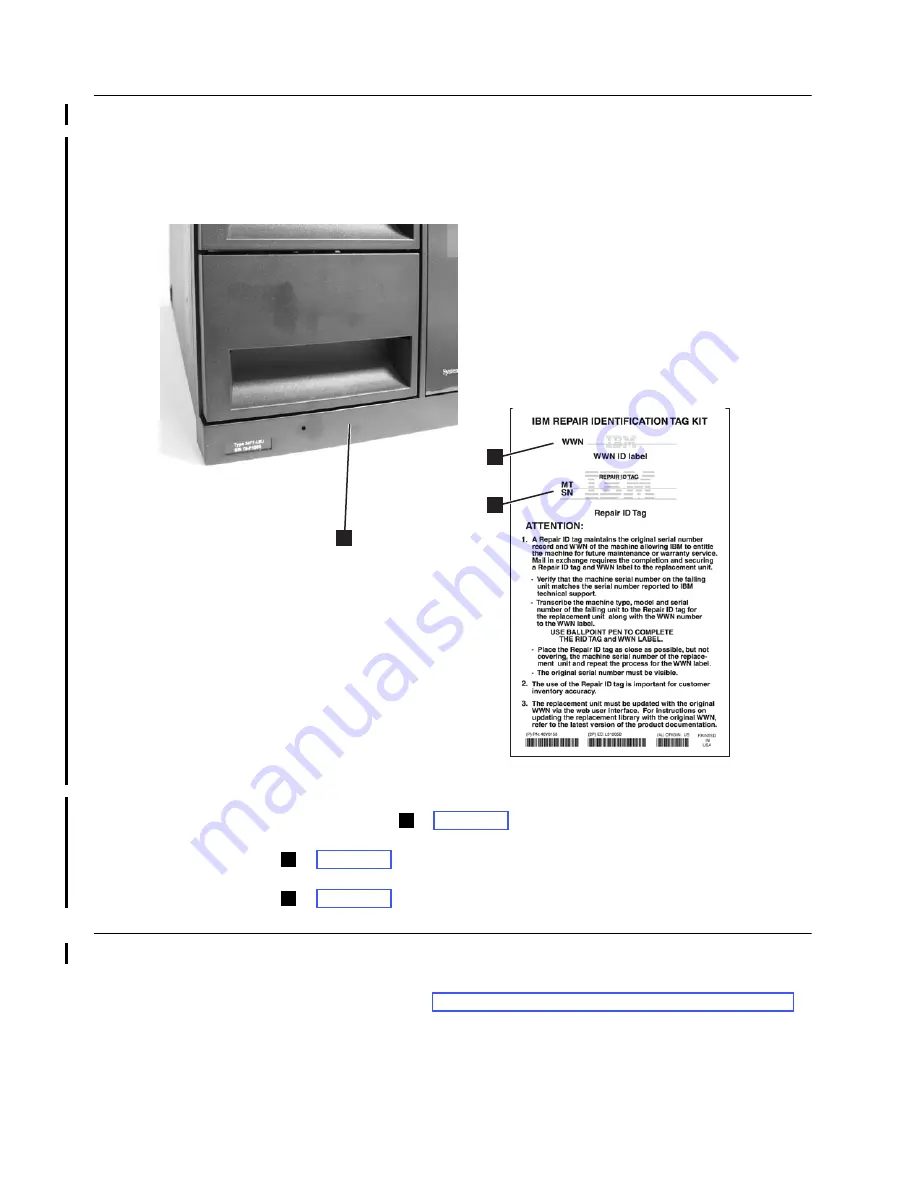
Applying a RID Tag to a Library

A RID (Repair Identification) Tag maintains the original serial number record and 
WWN of the machine to ensure that your warranty coverage, if applicable, is not 
interrupted. The tag is important for customer inventory accuracy. Follow the 
instructions on the RID tag precisely.

Figure 7-24. RID tag placement

1.

Copy the machine type (MT) and serial number (SN) from the old library onto 
the Repair ID tag (  in Figure 7-24).

2.

Copy the Worldwide Name (WWN) from the old library onto the WWN ID label 
 in Figure 7-24).

3.

Place the RID tag close to, but not covering, the serial number on the new library 
 in Figure 7-24). Repeat for the WWN ID label.

End of Call

1.

If any cartridges were removed from the library, give them to the customer.

2.

Record your activity in Chapter 10, “History of Service Activity,” on page 10-1.

3.

Return control of the library to the customer.

3

a34z0144

1

2

1

2

3

Summary of Contents for TS3400

Page 1: ...IBM System Storage TS3400 Tape Library Maintenance Information Machine Type 3577 GA32 0572 03 ...

Page 2: ......

Page 3: ...IBM System Storage TS3400 Tape Library Maintenance Information Machine Type 3577 GA32 0572 03 ...

Page 4: ... www ibm com storage lto This edition applies to the IBM System Storage TS3400 Tape Library Maintenance Information GA32 0572 03 and to the subsequent releases and modifications until otherwise indicated in new editions Copyright International Business Machines Corporation 2007 2008 All rights reserved US Government Users Restricted Rights Use duplication or disclosure restricted by GSA ADP Schedu...

Page 5: ...our comments to IBM via email at starpubs us ibm com or use the Reader s Comments form at the back of this publication Be sure to include the following The exact title of the document The part number The complete form number Where the problem is located for example a page number or table When you send information to IBM you grant IBM a non exclusive right to use or distribute the information in an...

Page 6: ...iv TS3400 Tape Library Maintenance Information ...

Page 7: ...ts 2 13 Drives 2 13 Power Supply Units 2 13 Media 2 14 Data cartridges 2 14 Cleaning cartridges 2 14 Capacity scaling and segmentation 2 15 Multi Path Architecture 2 15 Specifications 2 16 Maintenance Plan 2 16 Maintenance Start 2 17 Supported Servers Operating Systems and Software 2 17 Supported Device Drivers 2 17 Chapter 3 Library Components 3 1 TS3400 Tape Library 3 2 Front Panel Components 3 ...

Page 8: ...y Verify Diagnostics 7 5 Running Drive Diagnostics 7 6 Replacing a Drive 7 7 Connecting to the Ethernet Port 7 7 Connecting to the Serial Port 7 10 Service Functions using the Web User Interface 7 11 Running Encryption Key Path Diagnostics 7 11 Usage Statistics 7 12 Operator Interventions 7 13 Library Logs 7 13 Trace Data 7 15 Downloading Drive Logs 7 16 Downloading Library Logs 7 16 E mailing Log...

Page 9: ... 9 Adding a Tape Drive Canister Feature Code 4685 9 10 Replacing a Tape Drive Canister or FC 1663 Tape Drive Removal 9 11 Removal Procedure 9 11 Replacement Procedure 9 12 Replacing the Front Bezel 9 14 Removal Procedure 9 14 Replacement Procedure 9 16 Replacing the LCD Display Card 9 16 Removal Procedure 9 16 Replacement Procedure 9 18 Replacing the Drive Docking Card 9 19 Removal Procedure 9 19 ...

Page 10: ...eople s Republic of China Class A Electronic Emission Statement C 3 Taiwan Class A Electronic Emission Statement C 3 Korean Class A Electronic Emission Statement C 3 Japan VCCI Class A ITE Electronic Emission Statement C 3 Industry Canada Class A Emission Compliance Statement C 4 Avis de conformité à la réglementation d Industrie Canada C 4 Germany Electromagnetic Compatibility Directive C 4 Gloss...

Page 11: ...ng pin and label 6 9 6 10 Shipping pin storage location 6 9 6 11 Foot pads for desktop installation 6 10 6 12 Rack mount rail stud locations for front vertical rack rails 6 11 6 13 Rack mount rail stud locations for rear vertical rack rails 6 12 6 14 Rail mounting in rack front view 6 13 6 15 Rack ear mounting right side view 6 14 6 16 Rack ear mounting left side view 6 15 6 17 Sliding library int...

Page 12: ...g cover screw locations 2 9 29 9 31 LCD display card cable connector 9 30 9 32 LCD flat cable connector lock tab 9 30 9 33 Flat cable clamps on rear of library door 9 31 9 34 LCD display card cable disconnected 9 31 9 35 Center pillar removal 9 32 9 36 Flat cable plate screw location side 9 33 9 37 Back board flat cable connectors 9 34 9 38 Back board flat cable connector lock tab 9 34 9 39 Plasti...

Page 13: ...or the library 2 16 4 1 Menu commands and access privileges 4 7 5 1 Caution notice symbols 5 2 5 2 Examples of symbol use 5 2 6 1 Location criteria 6 1 6 2 Removing drive from another library 6 19 7 1 Drive rear panel LED indications 7 20 8 1 Updating Microcode in descending order of preference 8 11 8 2 Drive Ethernet Port LED Indications Model E06 Only 8 36 8 3 Response to ftp command mget offloa...

Page 14: ...xii TS3400 Tape Library Maintenance Information ...

Page 15: ...pport for attachment to 3592 C06 Controller FC 9014 IBM System Storage TS1120 and TS1130 Tape Drives and TS1120 Controller Operator Guide 3592 Models J1A E05 E06 EU6 J70 and C06 GA32 0556 IBM Encryption Key Manager Component for the Java Platform Introduction Planning and User s Guide GA76 0418 contains information to help you install configure and use the IBM Encryption Key Manager Component for ...

Page 16: ...t port Though uncommon some Model 3592 EU6 drives have an Ethernet port DNS server support added The DNS server setting allows the EKM NTP SNMP and SMTP servers to be specified using hostnames instead of numerical IP addresses Superuser accounts have been added to the Web User Interface These accounts provide access to the entire library and can perform functions such as moving media and loading d...

Page 17: ... page 1 25 Sense Key Definitions on page 1 26 Library Sense Data on page 1 27 Tape Drive Sense Data on page 1 28 Tape Drive FRU ID FID Data on page 1 33 Problem Area If Then Library Installation You need instructions during installation See Chapter 6 Installing the Library on page 6 1 Error Message The library issues an Error Code You will know when an Error Code has been issued when the Alarm or ...

Page 18: ...rary Verify diagnostic to identify the problem See Running Library Verify Diagnostics on page 7 5 You are experiencing a problem with the library and no Error Code was created Run the Library Verify diagnostic to identify the problem See Running Library Verify Diagnostics on page 7 5 You get repeated errors Open and close the cartridge magazines to ensure that all previous error handling is comple...

Page 19: ... 3 If the problem persists run Library Verify and Drive diagnostic tests See Running Library Verify Diagnostics on page 7 5 and Running Drive Diagnostics on page 7 6 4 If an error is detected replace the drive See Replacing a Tape Drive Canister or FC 1663 Tape Drive Removal on page 9 11 A bar code label cannot be read 1 Confirm that the bar code label is not damaged or missing 2 If necessary atta...

Page 20: ...play is stuck on initialization for extended period of time Lights are not correct on back of library 1 Run the Library Verify diagnostic test to identify the problem See Running Library Verify Diagnostics on page 7 5 2 Suspect the Library Control Blade or the Power Supply See Replacing the Library Control Blade LCB on page 9 8 and Replacing a Power Supply Unit on page 9 7 Encryption An error is d...

Page 21: ...KM If you are using library managed encryption perform the Key Path Diagnostic see Running Encryption Key Path Diagnostics on page 7 11 If the test fails a problem could exist with the IP address the Ethernet cable or the EKM server Perform the following 1 Check the Ethernet connection between the library and the EKM server 2 Check the TCP IP configuration of the library and the server 3 Check tha...

Page 22: ...ary chassis page 9 44 0010 Information acquisition from the DHCP server failed None Error code appears in library log 1 Confirm the server settings 2 Confirm the LAN cable connection 3 Cycle the power and try again 4 Replace the Library Control Blade page 9 8 5 Replace the TS3400 Tape Library chassis page 9 44 0011 Time acquisition from the NTP server failed 0020 Library Drive Interface LDI error ...

Page 23: ...11 5 Replace the TS3400 Tape Library chassis page 9 44 002C Library Drive Interface LDI error ACK response event timeout detected 1 Confirm the drive connection 2 Cycle the power and try again 3 Replace the Library Control Blade page 9 8 4 Replace the drive canister page 9 11 5 Replace the Drive Docking Card page 9 19 6 Replace the Back Board assembly page 9 37 7 Replace the TS3400 Tape Library ch...

Page 24: ...unication error detected CHK 0061 0062 Accessor EEPROM I2C communication abnormally terminated detected CHK 0062 0063 Accessor EEPROM checksum error detected CHK 0063 0070 Calibration failed because the Accessor contains a cartridge CHK 0070 Cycle the power and try again 0071 Calibration failed due to an empty magazine CHK 0071 0072 Calibration measurement error CHK 0072 0074 GET eject CTRG CHECK ...

Page 25: ...terface communication fails or is disconnected CHK 007F 1 Confirm the drive connection 2 Cycle the power and try again 3 Replace the Library Control Blade page 9 8 4 Replace the drive canister page 9 11 5 Replace the Drive Docking Card page 9 19 6 Replace the Back Board assembly page 9 37 7 Replace the TS3400 Tape Library chassis page 9 44 0080 X movement error 1 During X movement an error occurre...

Page 26: ... Replace the Library Control Blade page 9 8 3 Replace the Accessor assembly page 9 23 4 Replace the Accessor Flat Cable Plate assembly page 9 28 5 Replace the Back Board assembly page 9 37 6 Replace the TS3400 Tape Library chassis page 9 44 0091 Y movement error 2 During Y movement the motor lost sync with commanded position CHK 0091 0092 Y movement error 3 During initialization the motor lost syn...

Page 27: ...position was moved CHK 00A1 00A2 Swivel operation error 3 The swivel position sensor was detected after the GET position was moved CHK 00A2 00A4 During initialization the swivel origin could not be detected CHK 00A4 00A8 Swivel calibration error 1 During swivel calibration CTRG sensor OFF could not be detected CHK 00A8 Cycle the power and try again 00A9 Swivel calibration error 2 During swivel cal...

Page 28: ... and try again 2 Replace the Library Control Blade page 9 8 3 Replace the Accessor assembly page 9 23 4 Replace the Accessor Flat Cable Plate assembly page 9 28 5 Replace the Back Board assembly page 9 37 6 Replace the TS3400 Tape Library chassis page 9 44 00B9 Accessor error 2 An error was detected when moving the FWD position PP2 Accessor origin detected or FWD not detected CHK 00B9 00BA Accesso...

Page 29: ... CTRG calibration error 2 During CTRG calibration CTRG sensor ON could not be detected CHK 00C9 00D0 A checksum error was detected during updating the firmware CHK 00D0 1 Check the firmware file version 2 If firmware is correct reinstall the firmware 3 Replace the Library Control Blade page 9 8 4 Confirm Replace the power supply units page 9 7 5 Replace the Back Board assembly page 9 37 6 Replace ...

Page 30: ...E1 00E2 An error was detected in unit configuration data area stored in flash memory CHK 00E2 00E3 A checksum error was detected in the data stored in flash memory CHK 00E3 00F0 Sensor error 1 During blink check an Accessor origin sensor error was detected CHK 00F0 1 Cycle the power and try again 2 Replace the Library Control Blade page 9 8 3 Replace the Accessor assembly page 9 23 4 Replace the A...

Page 31: ...link check a magazine Lower sensor error was detected CHK 00FC 00FD Sensor error 12 During blink check an X origin sensor error was detected CHK 00FD Table 1 2 Drive error codes Code H Description Panel indication Action Required 0200 Invalid data was sent to Drive 1 NAK was detected CHK 0200 1 Confirm the drive connection 2 Cycle the power and try again 3 Replace the Library Control Blade page 9 ...

Page 32: ...rive canister page 9 11 4 Replace the Drive Docking Card page 9 19 5 Replace the Library Control Blade page 9 8 6 Replace the Back Board assembly page 9 37 7 Replace the TS3400 Tape Library chassis page 9 44 0300 Invalid data was sent to Drive 2 NAK was detected CHK 0300 1 Confirm the drive connection 2 Cycle the power and try again 3 Replace the Library Control Blade page 9 8 4 Replace the drive ...

Page 33: ...wer and try again 3 Replace the drive canister page 9 11 4 Replace the Drive Docking Card page 9 19 5 Replace the Library Control Blade page 9 8 6 Replace the Back Board assembly page 9 37 7 Replace the TS3400 Tape Library chassis page 9 44 Table 1 3 Web user error messages Title Message Issuing Panel Error modification failed Setting Users full Users You cannot remove yourself Users Parameter Err...

Page 34: ...es Tape not loaded Clean Drives Expired medium loaded Clean Drives Write protect error Clean Drives Cleaning execution failure Clean Drives I O Error File open failure Download Drive Logs Network Error User information access failure All Network data access failure Time server data access failure SNMP setting information access failure SMTP setting information access failure Library information ac...

Page 35: ...d the network condition setting Applet shutdown Displayed after 3 unsuccessful attempts using the Java Applet Table 1 3 Web user error messages continued Title Message Issuing Panel Table 1 4 Trap list Trap Name Enhanced Trap Event Type Description Alarm LED Error LED ColdStart authentication Failure enterpriseSpecification Vendor unique trap unitEventTrap error Library error Fatal error Drive err...

Page 36: ...epresent TapeAlerts that will be sent The MIB file should not be taken to mean that all traps that are defined in the MIB will be sent by the library or that they will be sent in the future TapeAlert Flags Supported by the Library Table 1 5 TapeAlert flags supported by the library Flag Number Flag Name Description Action Required 01 Library Hardware A The library mechanism is having trouble commun...

Page 37: ...system A redundant power supply has failed inside the library See Replacing a Power Supply Unit on page 9 7 Table 1 5 TapeAlert flags supported by the library continued Flag Number Flag Name Description Action Required Table 1 6 TapeAlert flags supported by the 3592 tape drives Flag Number Flag Name Description Action Required 1 Read warning Set when the tape drive is having problems reading data ...

Page 38: ...e is removed from the drive Set the write protect switch on the cartridge to OFF Ensure that the cartridge is not logically protected 10 No removal Set when an unload is attempted and SCSI Prevent Media Removal is set to ON The flag is cleared when the cartridge is removed from the drive If the error is an operator error no action is required if the error is a customer software error see the docum...

Page 39: ...a cleaning cartridge to be loaded and the loaded cartridge is not a cleaning cartridge Use a valid cleaning cartridge 25 Dual port interface error Set when a redundant Fibre interface port on the tape drive failed Replace the faulty component 26 Cooling fan failure Set when a tape drive or power supply cooling fan failed Replace the faulty component See Replacing a Tape Drive Canister or FC 1663 T...

Page 40: ...em persists replace the drive canister See Replacing a Tape Drive Canister or FC 1663 Tape Drive Removal on page 9 11 39 Diagnostics required Set when a tape cartridge or drive FID or ATTN DRV message is posted The flag is cleared when the drive is powered OFF Try different media Run drive diagnostic tests 50 Lost statistics Set when media statistics were lost at some time in the past None Status ...

Page 41: ...tation for those drivers to obtain the sense data Raw sense data as returned from the drive is documented in the IBM System Storage TS3400 Tape Library SCSI Reference 56 Unload failure The operation failed to unload a tape cartridge because of a drive hardware error or the tape may be damaged and stuck in the drive If the tape cartridge will not unload from the drive 1 If possible manually remove ...

Page 42: ...Sense Key Definitions Table 1 7 Sense key definitions SK Definition 00 No Sense 01 Recovered Error 02 Not Ready 03 Medium Error 04 Hardware Error 05 Illegal Request 06 Unit Attention 07 Data Protect 08 Blank Check 0B Aborted Command 0D Volume Overflow ...

Page 43: ...ion required 3A 02 Media not present tray open 80 05 During reprogramming mode 4 15 01 Mechanical position error 40 nn Diagnostic failure on component nn 80h ffh 44 00 Internal target failure 80 04 Fan alarm 80 07 NVRAM failure 5 1A 00 Parameter list length error 20 00 Invalid command operation code 21 01 Invalid element address 24 00 Invalid field in CDB 25 00 Logical unit not supported 26 00 Inv...

Page 44: ...ot ready format in progress 04 07 Unit not ready operation in progress 09 00 Track Following error 0C 00 WRITE error 11 00 Unrecovered READ error 11 01 Read retries exhausted 11 08 Unrecovered READ error incomplete block read 14 00 Recorded entity not found 14 01 Record not found 14 02 Filemark or Setmark not found 14 03 EOD not found 14 04 Block sequence error 15 01 Mechanical positioning error 1...

Page 45: ...elect failure 47 00 SCSI parity error 47 80 Read internal CRC error 47 81 Write internal CRC error 48 00 IDE message received 49 00 Invalid message error 4A 00 Command Phase error 4B 00 Data phase error 4C 00 Logical Unit failed self configuration 4E 00 Overlapped commands attempted 50 01 Write append position error WORM 51 00 ERASE failure 52 00 Cartridge fault 53 00 Media load or eject failed 53...

Page 46: ...ion Key Service Not Configured EE 02 Encryption Key Service Not Available EE 10 Encryption Key Required EE 20 Encryption Key Count Exceeded EE 21 Encryption Key Alias Exceeded EE 22 Encryption Key Reserved EE 23 Encryption Key Conflict EE 24 Encryption Key Method Change EE 25 Encryption Key Format Not Supported EE 26 Encryption Unauthorized Request dAK EE 27 Encryption Unauthorized Request dSK EE ...

Page 47: ... is no microcode dump currently available B 1 Indicates a microcode dump is available This information may be retrieved with the Read Buffer command and can be used by IBM Service personnel to analyze the state of the device The dump is lost at the next power off 4 Tape Directory Invalid B 0 Indicates the Tape Directory is valid B 1 Indicates the Tape Directory is invalid Note This field may not b...

Page 48: ... Reserved 46 49 Logical block number 50 52 Data set number x 000000 to x FFFFFF 53 Physical wrap number 54 55 Partition number x 0000 00FF 56 59 Relative LPOS 60 Logical wrap number 61 Last speed index 62 SARS drive relative quality best x 01 to worst FF 63 SARS media relative quality best x 01 to worst FF 64 69 Reserved 70 Cleaning required indicator 71 Reserved 72 78 Microcode EC number in ASCII...

Page 49: ...ster Encryption configuration installed during manufacturing is incorrect Drive canister must be replaced 51 Encryption Self Test POST HW 100 Drive Canister Encryption hardware power on self test POST failed Drive canister must be replaced 52 Encryption Self Test POST FW Encryption firmware power on self test POST failed See FID E6 in this table 53 Encryption Self Test Invoked 50 Drive Canister 50...

Page 50: ...l on page 9 11 86 The drive detected a drive hardware or media fault Cartridge problem Run the Media Test and Head Test See Running Drive Diagnostics on page 7 6 Drive canister problem See Replacing a Tape Drive Canister or FC 1663 Tape Drive Removal on page 9 11 87 The drive detected a cartridge media problem Ensure the cartridge has not been damaged Retry the job with a different cartridge Run t...

Page 51: ... drive detected that a drive dump has been written to flash memory Status message that a dump is in flash memory To offload a dump to flash or clearing flash dump memory see Downloading Drive Logs on page 7 16 F2 The drive detected a drive hardware or media fault See FID 86 in this table F4 The drive detected a problem with the RS 232 library to drive interface Reseat the drive canister If the pro...

Page 52: ...1 36 TS3400 Tape Library Maintenance Information ...

Page 53: ...rporates up to two IBM System Storage TS1120 Tape Drives Model 3592 E05 Machine Type 3592 Model E05 and or IBM System Storage TS1130 Tape Drives Model 3592 E06 Machine Type 3592 Model E06 and Model 3592 EU6 Machine Type 3592 Model EU6 which are ordered separately It comes with 4 Gbps dual ported switched fabric Fibre Channel attachment The TS1120 Tape Drive has a native data transfer rate of up Fr...

Page 54: ...ryption and associated IBM Encryption Key Manager EKM component in a wide variety of operating system environments including IBM System i IBM System p IBM System x IBM System z Linux HP UX Sun Solaris Linux and Microsoft Windows Encryption management methods supported are Application Managed System Managed and Library Managed The TS3400 Tape Library incorporates IBM s patented Multi Path Architect...

Page 55: ...rtridge magazines The upper and lower magazines are identical and can hold up to 9 cartridges each The front three slots of the lower magazine can be configured as I O Station slots The last two slots in the upper magazine can be configured as cleaning slots I O Station Figure 2 4 I O Station a34z0030 a34z0025 1 ...

Page 56: ... when a piece of media is bad degraded or invalid and indicates that operator intervention is required It is cleared when all invalid cartridges have been exported from the library It also is lit when a redundant power supply unit is powered OFF or loses power when the Autoclean function is enabled and no cleaning cartridge is in the cleaning slot or when the drive requests to be cleaned and no cl...

Page 57: ...ndow to monitor accessor and drive functions visually In addition to messages on the library Operator Panel individual drives can also display various messages on an 8 character drive message display visible through the view window For example the cartridge bar code is displayed on the drive message display when a cartridge is loaded into the drive Serial Number Label The machine type and serial n...

Page 58: ...y The LCB stores vital product data VPD such as library settings serial number library logs and Accessor calibration backup data An Ethernet port in Figure 2 7 on the LCB is used to connect the library to a network The LED in Figure 2 7 on the rear of the LCB is an Ethernet link activity indicator The RS 232 serial port in Figure 2 7 on the LCB is for use for IBM engineering purposes only a34z0029...

Page 59: ...lots in the rear of the library If a tape drive slot is empty a metal plate covers the empty drive slots to prevent debris from entering the library Fibre Channel tape drives can be directly attached to a host or a Storage Area Network SAN using dual ported switched fabric 4Gbps Fibre Channel host interface connectors in Figure 2 8 and Figure 2 9 Besides a traditional host E06 a14m0239 7 1 2 4 6 8...

Page 60: ...ll E06 and EU6 drives are encryption capable Not all E05 drives are encryption capable Look for the encryption capable label in Figure 2 9 No Model E06 drives and not all Model EU6 drives have an encryption capable label The rear panel has 5 LEDs in Figure 2 8 and Figure 2 9 to display various drive statuses For more information on the drive LEDs Interpreting LEDs on page 7 17 Port 0 and Port 1 Fi...

Page 61: ...o the Operator Panel Web User Interface and to e mail and SNMP notification recipients The library is powered ON when the power supply switch in Figure 2 10 on the rear panel is ON the library has no independent power switch on the front panel The power supply LED in Figure 2 10 on the rear panel also indicates when power is turned ON The power system of the library contains the following componen...

Page 62: ...by two vertical guide shafts and its tilt is controlled using three sets of rack and pinion gearing with synchronized rotation The Picker in Figure 2 12 rotates or swivels on a swivel plate assembly using a combination of swivel motor and gears The Picker has a finger that enables it to grab tape cartridges and move them to and from the I O Station storage slots and drives The Bar Code Reader in F...

Page 63: ...in the drive itself with the use of an Encryption Key Manager EKM helping to avoid the need for host based encryption of data with a concurrent drain on host performance or the use of specialized encryption appliances Dynamic Speed Matching To improve system performance the 3592 tape drives use a technique called dynamic speed matching to adjust its native uncompressed data rate to the slower data...

Page 64: ...pe Drive Removal Feature Code 1663 Feature Code 1663 is required for removing a 3592 tape drive from the library before installing a drive upgrade or installing the drive slot cover plate if an upgrade is not being installed This feature code is not required when a failed drive is being replaced Tape Drive Installation Feature Code 4685 Feature Code 4685 is required when installing a 3592 tape dri...

Page 65: ...I commands for 5 minutes Slot locations 17 and 18 can be configured as cleaning cartridge slots for both automatic cleaning and manual cleaning If only one slot is allocated for cleaning cartridges slot location 18 is selected The cleaning slots are used for all drives in the physical library When the library has two cleaning cartridges the cartridge with the higher cleaning count usage is selecte...

Page 66: ... 3592 drive models This microcode ensures that a 3592 encrypted cartridge format can be recognized by any 3592 drive regardless of whether the drive is encryption enabled or not While the 3592 J1A is not supported in the 3577 tape library if the customer is going to be using the cartridges in a mixed scratch pool that could be used in a 3592 J1A in a different library the minimum code for the J1A ...

Page 67: ...ility matrix and ISV matrix can be found at this link Multi Path Architecture The library features the Storage Area Network SAN ready Multi Path Architecture which allows homogeneous or heterogeneous open systems applications to share the library s robotics without middleware or a dedicated server host acting as a library manager The SAN ready Multi Path Architecture makes sharing possible by lett...

Page 68: ...ng Drive temperature 16 to 32 C 60 to 90 F 1 to 60 C 34 to 140 F 30 to 60 C 22 to 140 F Relative humidity 20 to 80 5 to 80 5 to 100 Wet bulb temperature 23 C 73 F max 29 C 84 F max 29 C 84 F max Note The operating environment of the library must not conflict with the media storage requirements refer to the IBM System Storage TS3400 Tape Library Planning and Operator Guide The library may be capabl...

Page 69: ...ng procedures to access this material Note If you do not have Internet access and you need information about device drivers contact your Marketing Representative Using a browser type one of the following http www ibm com storage ftp ftp software ibm com storage devdrvr Using File Transfer Protocol FTP enter the following specifications FTP site ftp software ibm com IP Addr 207 25 253 26 Userid ano...

Page 70: ...2 18 TS3400 Tape Library Maintenance Information For more information about device drivers refer to any of the preceding directories ...

Page 71: ...age 3 4 Power Supply Unit on page 3 5 Library Control Blade LCB on page 3 5 Tape Drive on page 3 6 LCD Display Card on page 3 6 Accessor Assembly on page 3 7 Accessor Flat Cable Plate on page 3 8 Back Board on page 3 8 Drive Docking Card on page 3 9 Magazine Lock Release Mechanism on page 3 9 I O Station Lock Release Mechanism on page 3 10 Desktop Mounting Rubber Feet on page 3 10 Rack Mount Kit o...

Page 72: ... TS3400 Tape Library Figure 3 1 Tape library unit Front Panel Components Figure 3 2 Front view of the library a34z0073 1 2 6 3 4 5 a34z0074 Cartridge Magazines Operator Panel View Window Front Panel LEDs Control Keys Serial Number Label 1 4 2 5 3 6 ...

Page 73: ...e library 3 4 5 2 4 1 a34z0075 8 7 6 Drive cover plate Shipping pin storage slot Library Control Blade LCB Drive cover plate Power supply units Ethernet port Tape drive canister RS232C serial port for IBM engineering use at the direction of your next level of support 1 5 2 6 3 7 4 8 ...

Page 74: ...ce Information Cartridge Magazines Figure 3 4 Tape cartridge magazine I O Station Figure 3 5 I O Station Front 3 slots in lower cartridge a34z0076 1 a34z0077 I O Station when enabled occupies the front 3 slots in the lower cartridge 1 ...

Page 75: ...er supply unit Library Control Blade LCB Figure 3 7 Library Control Blade 2 1 3 a34z0078 4 Power switch Power LED Power socket Thumbscrew 1 3 2 4 2 1 a34z0079 3 5 4 Ethernet port for network connection Thumbscrews Ethernet link LED Handle RS232C serial port 1 4 2 5 3 ...

Page 76: ...3 6 TS3400 Tape Library Maintenance Information Tape Drive Figure 3 8 Tape drive in canister LCD Display Card Figure 3 9 LCD display panel with front bezel removed 1 a34z0080 Tape drive LEDs 1 a34z0081 ...

Page 77: ...Chapter 3 Library Components 3 7 Accessor Assembly Figure 3 10 Accessor assembly 1 2 a34z0082 3 Accessor assembly Bar code reader Picker 1 3 2 ...

Page 78: ... TS3400 Tape Library Maintenance Information Accessor Flat Cable Plate Figure 3 11 Accessor FFC cable plate Back Board Figure 3 12 Library back board rear view from power supply housing 1 a34z0083 a34z0084 ...

Page 79: ...Chapter 3 Library Components 3 9 Drive Docking Card Figure 3 13 Drive docking card Magazine Lock Release Mechanism Figure 3 14 Magazine lock release mechanism a34z0085 a34z0086 ...

Page 80: ...Information I O Station Lock Release Mechanism Figure 3 15 I O Station lock release mechanism Desktop Mounting Rubber Feet Figure 3 16 Desktop mounting rubber feet 2 1 a34z0087 I O Station lock release button I O Station lock 1 2 a34z0088 ...

Page 81: ...Chapter 3 Library Components 3 11 Rack Mount Kit Figure 3 17 Rack mount kit brackets and rails a34z0089 2 3 1 Rack mount kit rails Clip on bezels Mounting brackets 1 3 2 ...

Page 82: ...gram Library Control Card LCD Display Card LCD Module Switch 4 LED 3 Buzzer Motor Sensor 2 Drive Canister 1 Solenoid 3 Motor 2 Sensor 3 EEPROM Motor Sensor 3 Bar Code Reader Redundant P S 1 Back Board Drive Canister 2 Drive Docking Card Redundant P S 2 Accessor Sensor 4 Ethernet RS 232C AC AC a34z0155 ...

Page 83: ... SH7616 DRV I F SCIF1 MAC PHY MAG RJ 45 FLASH 1 SDRA M 2 RS 232C D sub 9 OP Panel DAC 15 625MHz RESET Motor Driver Sensor X12 SDRAM 2 4M 16 2 RS 422 BCR FLASH 2 128k 16 RTC EEPROM 32 768Hz FPGA SCIF2 RS 422 DRV I F UART UART I O Port I2C MOTOR CONTROL Solenoid Driver FLASH 1 4M 16 2 Battery 25MHz Address Data Bus a34z0156 ...

Page 84: ...3 14 TS3400 Tape Library Maintenance Information ...

Page 85: ... installed on your host computer for full functionality and is best viewed using Internet Explorer 6 0 or higher Internet Explorer 7 0 or higher is required for IPv6 Operator Panel The Operator Panel is located on the front bezel of the library The Operator Panel displays library status information and menu commands used to execute library management functions in response to the Control Keys locat...

Page 86: ...ms available to the user Status Display Screen The status display screen indicates the current library status The status display screen is displayed automatically after a logout timeout period expires with no user input Press the Cancel control key on the Login screen to return to the status display screen Figure 4 2 Status display screen The library status screen has the following elements The Ac...

Page 87: ...ducts a tape inventory of the cartridge magazines and tape drives This process can take several minutes The login screen is displayed when the inventory is complete Figure 4 3 Login screen To login 1 Press the Enter control key to display the User Login password screen Figure 4 4 Login password screen 2 Enter the 4 character password for the tape library The factory default password is 0000 The pa...

Page 88: ...he library and drive firmware and to download error logs drive logs and library logs from the library Before the TS3400 Tape Library can be managed over a network using the Web User Interface you must set up the initial network configuration of the library using the Operator Panel Logging in to the Web User Interface To log in to the Web User Interface from Internet Explorer you need to enter the ...

Page 89: ...r account service Password Contact your next level of support After entering your Account name and Password use your mouse to click Login or press the Enter key For information on Administrator Service and User account privileges see User Privileges on page 4 6 Common Header Elements All Web User Interface windows except for the Login screen contain the following common elements in the header Help...

Page 90: ...m actions that affect the physical library Superusers are allowed to operate the physical and logical libraries but not perform actions that affect the library configuration Administrator users are allowed access to the entire physical library and all of its logical libraries including configuration One and only one administrator user must be assigned the login name admin Service users are allowed...

Page 91: ...dges X X X Unload Drives X X X Cartridge Attributes X X X Clean Drives X X X Library State X X X Inventory X X X CONFIGURE LIBRARY User Access X X Physical X X Logical X X Network X X Encryption X X Date and Time X X Notifications X X Save Restore X X SERVICE LIBRARY Key Path Diagnostics X X Operator Interventions X X X X View Library Logs X X X X Trace X Download Drive Logs X Download Library Log...

Page 92: ...4 8 TS3400 Tape Library Maintenance Information ...

Page 93: ...ethal or extremely hazardous to people A lightning bolt symbol always accompanies a danger notice to represent a dangerous electrical condition A sample danger notice follows Danger Notice on page 5 1 Caution Notice on page 5 2 Area of Application on page 5 3 Possible Safety Hazards on page 5 3 Class I Laser Product on page 5 3 Before Working on Equipment on page 5 4 Performing the Safety Inspecti...

Page 94: ...f the unit Weight symbols are accompanied by an approximation of the product s weight Table 5 2 Examples of symbol use The controller card contains a lithium battery CAUTION The battery is a lithium ion battery To avoid possible explosion do not burn Exchange only with the IBM approved part Recycle or discard the battery as instructed by local regulations In the United States IBM has a process for...

Page 95: ...t first correcting the problem Possible safety hazards are Electrical An electrically charged frame can cause serious electrical shock Mechanical Hazards such as a safety cover missing are potentially harmful to people Chemical Do not use solvents cleaners or other chemicals not approved for use on this product Repair any of the preceding problems before you use the library Class I Laser Product T...

Page 96: ...gency Operating Mode Emergency operations are meant for Manual inserts and retrievals of media Manual operation of the drives Sharp Edges on Tape Drives 3592 E05 tape drives with the following serial numbers may have burrs or sharp edges in the areas that are highlighted in Figure 5 1 When working with tape drive canisters carefully handle the sheet metal case and cover of the canister and the can...

Page 97: ...age such as a pinched cut or frayed cord 7 Check the tape drive s Fibre Channel cables for damage 8 Check the cover of the library for sharp edges damage or alterations that expose its internal parts 9 Check the cover of the library for proper fit It should be in place and secure 10 Check the product label at the rear of the library to make sure it matches the voltage at your outlet ac Grounding I...

Page 98: ...5 6 TS3400 Tape Library Maintenance Information Figure 5 2 ac grounding inspection a05m0246 Vac x 10 0 0 Vac 0 1 0 1 ...

Page 99: ...ower cord with a grounded attachment plug has been provided Use only properly grounded outlets All power cords use an appliance coupler that complies with the International Electrotechnical Commission IEC Standard 320 Sheet C13 If the power cord that you receive does not match your receptacle contact your local dealer Power cords used in the United States and Canada are listed by Underwriter s Lab...

Page 100: ...ch as Covers Hazard alert messages Warning signs Grounding wires Clothing must be in agreement with the following safety rules No metal fasteners Should be close fitting so that it cannot be caught in moving machine parts Buttoned or rolled up sleeves Place the ends of a scarf or tie into the clothing For long hair use a protection that fully covers it Remove watch rings and jewelry When handling ...

Page 101: ...xed drawer and should not be moved for servicing unless specified by the manufacturer Attempting to move the drawer partially or completely out of the rack may cause the rack to become unstable or cause the drawer to fall out of the rack R001 Always lower the leveling pads on the rack cabinet Always install stabilizer brackets on the rack cabinet To avoid hazardous conditions due to uneven mechani...

Page 102: ...ing movement Do not use a ramp inclined at more than ten degrees Once the rack cabinet is in the new location do the following Lower the four leveling pads Install stabilizer brackets on the rack cabinet If you removed any devices from the rack cabinet repopulate the rack cabinet from the lowest position to the highest position If a long distance relocation is required restore the rack cabinet to ...

Page 103: ...les aux systèmes utilisés à travers l Union européenne Conformément à la directive ladite étiquette précise que le produit sur lequel elle est apposée ne doit pas être jeté mais être récupéré en fin de vie In accordance with the European WEEE Directive electrical and electronic equipment EEE is to be collected separately and to be reused recycled or recovered at end of life Users of EEE with the W...

Page 104: ...her reclaimed upon end of life per this Directive Les batteries ou emballages pour batteries sont étiquetés conformémentaux directives européennes 2006 66 EC norme relative aux batteries et accumulateurs en usage et aux batteries et accumulateurs usés Les directives déterminent la marche à suivre en vigueur dans l Union Européenne pour le retour et le recyclage des batteries et accumulateurs usés ...

Page 105: ...s includes the cost of the environmental management of their waste For California Perchlorate Material special handling may apply See http www dtsc ca gov hazardouswaste perchlorate The foregoing notice is provided in accordance with California Code of Regulations Title 22 Division 4 5 Chapter 33 Best Management Practices for Perchlorate Materials This product part or both may include a lithium ma...

Page 106: ...5 14 TS3400 Tape Library Maintenance Information ...

Page 107: ...eduction on page 6 19 Connecting the Power Cords on page 6 20 Verifying Library and Drive Operation on page 6 20 Connecting the Host Interface Cable and Network Cable on page 6 21 Configuring the Library on page 6 22 Table 6 1 Location criteria Criteria Definition Room temperature 16 to 32 C 60 to 90 F Voltage 100 to 240 Vac Note that the power switch is located on the rear of the library and must...

Page 108: ...nal rack mount kit Drive canisters if ordered Important If any of the contents of your shipment are damaged or missing please call the appropriate number listed on the Quality Hotline card Removing Components to Reduce Library Weight You can install the library in a rack or on a desktop Remove the following components from the library to reduce the weight Power supply units Library Control Blade L...

Page 109: ...Chapter 6 Installing the Library 6 3 Figure 6 1 Components removed to reduce weight a34z0177 ...

Page 110: ...ove each power supply installed in the library 1 Loosen the blue thumb screw in Figure 6 2 on the power supply by turning it counterclockwise 2 Grasp the handle in Figure 6 2 and slowly pull the power supply toward you while supporting it from underneath 3 Repeat this procedure for each library power supply a34z0059 1 2 1 2 ...

Page 111: ...rary Control Blade by turning them counterclockwise 2 Place two fingers under the handle in Figure 6 3 and slowly pull the Library Control Blade toward you while supporting it from underneath Removing the Cartridge Magazines To unlock the cartridge magazines manually 1 On the rear panel locate the access hole for the cartridge magazine locking release mechanism to the right of the power supply uni...

Page 112: ...y push the lock mechanism to release the lock and eject the cartridge magazines Figure 6 5 Cartridges released 3 If the I O Station is enabled the lower cartridge magazine cannot be fully removed from the library You must release the I O Station lock after releasing the cartridge magazine lock in order to withdraw the cartridge magazine from the library a34z0001 1 a34z0002 1 ...

Page 113: ...ation locking mechanism below the I O Station in Figure 6 7 Figure 6 7 I O Station lock release access hole b Insert the 2 mm hexagonal wrench or a similar tool into the lock release access hole and gently push to release the locking mechanism 4 Remove the cartridge magazines from the front of the library a34z0110 1 a34z0024 1 ...

Page 114: ... Figure 6 8 Shipping pin and label Important The shipping pin prevents the library Accessor from moving during shipment and must be removed before the library is powered ON The shipping pin is attached to an orange label and is taped in place on the right side of the library a34z0040 1 ...

Page 115: ...ing pin 1 Remove the orange label and the shipping pin from the bottom right side of the library Figure 6 9 Shipping pin and label 2 Store the shipping pin and label in the storage location on the rear panel Figure 6 10 Shipping pin storage location a34z0138 a34z0139 ...

Page 116: ...llowing the procedures in Removing Components to Reduce Library Weight on page 6 2 Figure 6 11 Foot pads for desktop installation To install the library foot pads 1 Being very careful lay the library on its side 2 Using a 2 Phillips screwdriver install the foot pads in Figure 6 11 on the bottom of the library chassis at the six locations indicated 3 Carefully return the library to an upright posit...

Page 117: ...ry read the safety information in Rack Safety on page 5 9 Also verify that no foot pads are installed on the bottom of the library The library requires 5U rack space in an EIA standard sized rack One unit 1U of vertical rack space is equal to 4 45 cm 1 75 in and contains three holes with equidistant centers of 1 59 cm 0 625 in The boundary between each 1U rack space is identified by two holes sepa...

Page 118: ... rails on the front and rear of the rack 2 Identify and mark the holes in the vertical rails corresponding to the rail studs located on the front and back of each shelf rail included in the Rack Mount Kit The rail studs go into the following positions a In the front vertical rack rails in Figure 6 12 Middle hole in the first bottom 1U space Middle hole in the fifth top 1U space b In the rear verti...

Page 119: ... between front and rear vertical rail posts 2 Insert the studs on the front of the sliding rail into the holes marked on the front vertical post 3 Insert centering screws in each of the vertical posts two screws on each of the front rails and finger tighten The screws occupy the following rack locations in Figure 6 12 Bottom hole in the second 1U space Top hole in the fourth 1U space 4 From the re...

Page 120: ... 6 From the front of the rack visually verify that the rail is aligned properly with the rack 7 Repeat this procedure for the other rail 8 Tighten the screws to finish installing the rails Installing the Rack Ear Mounting Brackets Rack ear mounting brackets are installed on the front of the library to retain the library on the rack shelves The two mounting brackets are identical and can be attache...

Page 121: ...6 15 and Figure 6 16 1 Attach a mounting bracket to the front right side of the library The rear two holes on the mounting bracket are recommended for normal installations However the front two holes can be used if space at the rear of the library is a premium 2 Repeat this procedure for the other mounting bracket a34z0036 1 1 ...

Page 122: ...rary Weight on page 6 2 Figure 6 17 Sliding library into the rack To place the library in the rack 1 With a person on each side of the library lift the library 2 Slide the library partially onto the rail shelves in the rack 3 Push the library into the rack until the mounting bracket contacts the front vertical rail posts 4 Insert and tighten the thumb screws on the mounting brackets in Figure 6 18...

Page 123: ...Chapter 6 Installing the Library 6 17 Figure 6 18 Clip on bezels Figure 6 19 Library front panel clip on bezel a34z0038 1 2 a34z0140 ...

Page 124: ... Figure 6 20 from the rear panel of the library Store the cover plate and retaining screw for future use Figure 6 20 Drive cover plate 2 Carefully slide the drive canister into the fixed tray assembly 3 Hold the locking lever in Figure 6 21 up to ensure the tabs on both sides of the lever clear the frame Figure 6 21 Front and rear view of tape drive 1 a34z0017 1 E05 FC SHORT WAVE 4G b SEC PORT0 PO...

Page 125: ... 4 Hold the locking lever in Figure 6 21 up to ensure the tabs on both sides of the lever clear the frame 5 Grasp the drive canister handle in Figure 6 21 and carefully but firmly push the drive into position Ensure that the connectors to the right correctly align and fully engage with the drive docking card 6 Lower the locking lever in Figure 6 21 until it snaps into place Installing Library Comp...

Page 126: ... by toggling the power switches on each power supply to the ON position 4 Wait for the library to initialize This will take approximately 10 minutes Note If the Operator Panel does not initialize check all cable connections and ensure that all cartridge magazines are tightly closed and all power supply switches are in the ON position Verifying Library and Drive Operation To verify the library is o...

Page 127: ...read verify test The cartridge is then moved to the second drive if installed and the test is repeated When the test is done the library tells the drive to eject the cartridge and then the cartridge is moved back to the I O Station The bar code is read again and compared with the value stored earlier 7 Check the result of the test PASSED or FAILED reported on the Operator Panel 8 Press any key and...

Page 128: ...brary a crossover cable may be required Figure 6 24 Ethernet cable Configuring the Library The customer is responsible for configuring the library and the drives including encryption partitions and other configuration settings Refer the customer to the configuration instructions in the IBM System Storage TS3400 Tape Library Planning and Operator Guide Note If this library is attached to an IBM Sys...

Page 129: ...can be notified immediately by setting up e mail event notification and or SNMP trap notification The type of event that generates e mail notification or SNMP trap notification can be selected to limit the number of events to a specific priority level Library Error Messages and Resolutions When a library event occurs the event is logged into Flash memory on the Library Control Blade The library er...

Page 130: ... to display errors with specific sense data code types Selecting a specific entry displays additional information in the Detail panel comprising Index number of the error Date and time the error occurred Error code Description of the error Observe the LEDs on all library components to determine exactly which part is failing See Interpreting LEDs on page 7 17 for more information See Start Service ...

Page 131: ... library online after you finish adding removing and replacing all necessary parts See Taking the Library Offline Online on page 7 23 13 Clear all open Operator Interventions 14 Verify that your host applications can communicate with all drives and the library 15 Generate another log of the status of the library after verifying that the library is repaired and running smoothly 16 Complete the step...

Page 132: ...eck the error log 1 Log into the Operator Panel 2 Press the Down button to select Service Mode and press Enter 3 Press the Down button to select Error Log and press Enter 4 If an error has occurred press the Down button to select an error and press Enter to display specific error information You can check the meaning of error codes in Error Codes on page 1 5 Checking Mechanical Movement Statistics...

Page 133: ...n to select Service Mode and press Enter 3 Press the Down button to select Diagnostics and press Enter 4 Select Library Verify and press Enter Follow the on screen instructions The library performs a Power ON Self Test POST the normal test sequence performed when the library is turned ON to ensure that the library hardware is functional Then the library tests communications with the tape drives ov...

Page 134: ...ally occur when the library is powered ON POST When prompted load a CE scratch cartridge to run the calibrate drive read write and tape motion tests These tests calibrate the read write channel to optimum settings run a long read write test using all servo positions and exercise all of the tape motion functions of the drive Takes up to 30 minutes Media Test Runs tests on the tape cartridge media W...

Page 135: ...acement command takes the drive offline from the fibre channel host and causes the drive to save a log to flash memory After replacing a drive the Finishes Replacement command stores the original drive s settings including the serial number emulation mode WWNodeName and other settings into the VPD of the replacement drive If the drive microcode level is below the revision level on the drive you re...

Page 136: ...ress of the library a From the top menu of the Operator Panel press the Down button to select View Settings and press Enter b Press the Down button until the IP Address setting is displayed and make a note of the IP address c Press the Cancel button twice to log out of the Operator Panel 4 On the laptop open Internet Explorer or compatible browser 5 In the browser address field enter your library ...

Page 137: ...s 7 Enter the service user login account name and password Special instructions when servicing the library including the server user login information are provided on the web at http snjlnt02 sanjose ibm com tape tapetec nsf pages opensystems 8 Click Login The System Summary window appears For Web User Interface functions specific to the Service User see Service Functions using the Web User Interf...

Page 138: ...port 1 Connect a null modem cable between the laptop and the serial port in Figure 7 11 on the LCB 2 Start a Hyperterminal session by clicking Start Programs Accessories Communications Hyperterminal 3 Enter a name for the session For example TS3400 4 Select the COM port that the library is connected to 5 Enter the following port settings Bits per second 38400 Data bits 8 Parity None Stop bits 1 Fl...

Page 139: ...ve Test The library performs a drive communication test to confirm communication with the drive Ethernet Test The library pings each EKM server IP address and records the result EKM Path Test The library performs an EKM communication test for each EKM server IP address that passed the Ethernet Test The library sends a LDI Crypto Diagnostics command to the drive This drive command causes the drive ...

Page 140: ... is the same as the information that can be accessed from the Operator Panel see Checking Mechanical Movement Statistics on page 7 4 To download accessor statistics 1 Expand Service Library if necessary and click on Usage Statistics in the left navigation pane of the Web User Interface 2 Click Refresh to read the Accessor statistics from the library 3 Click Download to download the statistics and ...

Page 141: ... Service Library if necessary and click on Operator Interventions in the left navigation pane of the Web User Interface 2 Select the Unit Type options and Event Level filter options to reduce the number of events displayed as needed 3 Click Refresh to display the filtered list 4 Click on an event in the Index List to display the data for that event in the Detail pane 5 Click Download to download t...

Page 142: ...ributes The Index list displays the most recent error log 000 to the oldest nnn discarding the oldest error records when the log is full There are 2 types of error data displayed in the library log with different Code attributes Library Drive sense data Sense key ASC ASCQ For example a 6 41 FE error states a drive error message was detected Selecting log entry 000 shows that the library detected t...

Page 143: ... data screen Use Service Library Traces to display a trace history of errors that have occurred The summary can be filtered to display the type of errors occurring within a given time period To download trace information 1 Expand Service Library if necessary and click on Traces in the left navigation pane of the Web User Interface 2 Select the Trace Type and Number of Minutes filter options to red...

Page 144: ...a file on your host computer To clear the drive data log from flash memory after saving to a file 1 Take the library offline See Taking the Library Offline Online on page 7 23 2 Expand Service Library if necessary and click on Download Drive Logs in the left navigation pane of the Web User Interface 3 Select the drive in the Target Drive pop up menu 4 Select the Clear radio button option 5 Click t...

Page 145: ...er Interface select Service Library Download Drive Logs select the drive specify a file name and location and click Download See Downloading Drive Logs on page 7 16 4 When requested by IBM attach the library log and drive logs to an email message and send it to IBM Technical Support for further diagnosis Interpreting LEDs Light emitting diodes LEDs provide a visual indication about the status of c...

Page 146: ...n page 2 6 When lit the LED indicates Ethernet network link traffic between the library and the network Tape Drive LEDs Operator interventions typically report all problems related to tape drives including error codes and tape alerts By observing the messages on the LED panel in Figure 7 20 at the front of the tape drive and the blinking pattern of port and status LEDs in Figure 7 21 at the rear o...

Page 147: ...es that there is performance related data stored within the drive dynamic random access memory RAM This dump data can be retrieved by a service representative for troubleshooting purposes Clean required means that the drive needs to be cleaned by means of a cleaning cartridge WORM tape indicates that the cartridge currently in the drive is a WORM cartridge Drive Rear Panel LEDs Figure 7 21 Drive r...

Page 148: ...o light detected through Fibre Channels Fibre channel cable disconnected Port not in use Fibre wrap plug installed on the port Drive not returned to operator mode still in CE offline mode or CE online mode Green Fibre Channel connections are detecting light but no data is being transferred Wrap tools are installed or drive canister is offline to controller or host Fibre Channel connections are goo...

Page 149: ...rary operations It will be several minutes before the library reboots Important After the update process starts you must wait until the library reboots Do not attempt to interrupt the process in any way or the upgrade will not be successful Updating Drive Firmware Drive firmware is best updated using the drive s application Fibre Channel interface A very fast method to load drive code is using ITD...

Page 150: ...with the drive through the library to load and unload a test cartridge thereby exercising some library functions Scans to find and displays all IBM devices The tool will not display any non IBM devices The Help selection explains the required syntax as well as a brief explanation of the particular function A Readme text file will be posted with the exe file for a thorough explanation of initial to...

Page 151: ...x html 2 Install the MIB file on your SNMP server Refer to your server application documentation for instructions Reseating Cables To reseat external library cables perform the following steps 1 Locate the following cables on the rear panel of the library a Dual ported switched fabric 4Gbps Fibre Channel attachment for each drive see Figure 6 23 on page 6 21 b Ethernet cable for connection to a ne...

Page 152: ...ion and press Enter 2 Select Library Settings and press Enter 3 Select Online Offline and press Enter 4 Select Online and press Enter 5 Press Cancel to return to the Configuration menu 6 Press Cancel to return to the top level menu 7 Press the Down button to select Logout and press Enter To take the library online using the Web User Interface 1 Expand Manage Library if necessary and click on Libra...

Page 153: ...ower switch on each power supply to the OFF O position to shut down the library 5 Disconnect the library s power cords from their electrical source Restarting 1 Connect all power cords to their electrical source 2 Toggle the power switch on each power supply to the ON position to restart the library 3 When the library is fully initialized the login screen displays on the Operator Panel 4 Ensure th...

Page 154: ... tag placement 1 Copy the machine type MT and serial number SN from the old library onto the Repair ID tag in Figure 7 24 2 Copy the Worldwide Name WWN from the old library onto the WWN ID label in Figure 7 24 3 Place the RID tag close to but not covering the serial number on the new library in Figure 7 24 Repeat for the WWN ID label End of Call 1 If any cartridges were removed from the library gi...

Page 155: ...splay a dialog to enter a file name and to select a location to save the drive dump Normal data log Forced data log 6 Click the Download button to download the drive log and save to a file To clear the drive log from flash memory after saving to a file 1 Take the library offline See Taking the Library Offline Online on page 7 23 2 Expand Service Library if necessary and click on Download Drive Log...

Page 156: ...into the system floppy diskette drive 5 When the prompt appears format the diskette by typing format and press Enter 6 Start the tape utility program by typing tapeutil at the prompt 7 Select Tape Drive Service Aids option from the menu and press Enter 8 Select Read Dump from the following panel and press Enter 9 Select a Device and press F7 Commit from the following panel You must press F7 Commit...

Page 157: ...tile and is lost if you press the Reset pushbutton or power OFF the device 1 At the drive service panel verify that the drive is Online 2 Verify that the drive is unloaded 3 Verify that the drive is not in use by another host 4 Start the tape utility program by typing IBMtapeutil at the prompt IBM Tape Device Selection Menu 900000 Select One of the devices listed below NAME LOCATION TYPE rmt2 00 0...

Page 158: ... 9 Mode Sense Page 4 Test Unit Ready 10 Switch Tape Changer Device 5 Reserve Device 11 Create Special Files 6 Release Device 12 Query Driver Version Q Quit IBMtapeutil Medium Changer Commands 60 Element Information 65 Load Unload Medium 61 Position To Element 66 Initialize Element Status 62 Element Inventory 67 Prevent Allow Medium Removal 63 Exchange Medium 68 Initialize Element Status Range 64 M...

Page 159: ...eserve Device 11 Create Special Files 6 Release Device 12 Query Driver Version Q Quit IBMtapeutil Tape Commands 20 Rewind 33 Set Block Size 21 Forward Space Filemarks 34 Retension Tape 22 Backward Space Filemarks 35 Query Set Tape Position 23 Forward Space Records 36 Query Tape Status 24 Backward Space Records 37 Load Tape 25 FSFM 38 Unload Tape 26 BSFM 39 Lock Tape Drive Door 27 Space to End of D...

Page 160: ...e tapeutil f dev rmt nst o sdp z file v Note The diagnostic dump procedure may also be performed by using the menu driven interface of the tapeutil program To invoke the tapeutil program in this format enter the following command then choose option 1 to open the device followed by option 5 to force a dump and option 6 to store the dump opt IBMtape tapeutil Offloading Dumps to HP UX System using TA...

Page 161: ...erformed by using the menu driven interface of the ntutil program To invoke the ntutil program in this format enter the common commands and option 80 to Force Dump Remember that the dump goes to the default drive directory 1 Verify that the IBM tape subsystem is powered ON and online 2 Verify that the tape drive has a tape cartridge loaded 3 Start ntutil and open the drive by performing Step 1 thr...

Page 162: ...cting the drive 10 Enter the filename tmp 3592 dmp in the destination field You must press F7 Commit after entering the filename IBM Tape Device Service Aid Menu 700000 Select One of the Service Aids to be performed Force Microcode Dump Perform a microcode dump of the system The dump is stored in the device After the dump is performed it must be read using Read Dump Read Dump Transfer a dump from ...

Page 163: ...rs when the dump is available It remains on the screen to indicate that trace data is stored in the device Note Trace data is volatile and is lost if you press the Reset pushbutton or power OFF the device 1 At the drive service panel verify that the drive is Online 2 Verify that the drive is unloaded 3 Verify that the drive is not in use by another host 4 Locate the control unit diskette drive and...

Page 164: ...rocode dump of the system The dump is stored in the device After the dump is performed it must be read using Read Dump Read Dump Transfer a dump from the tape device to a host file diskette or a tape cartridge Microcode load Download microcode from host file or diskette to tape device via SCSI bus Error Log Analysis Analyze system error log for device F3 Cancel F10 Exit IBM Tape Device Selection M...

Page 165: ...to copy a dump at the end of the data that is already present on the tape 5 At the prompt load a CE scratch tape and select Process Loaded Tape A screen indicates the status of the copy to medium Successful Copy or Unsuccessful Copy 6 When the dump to tape has completed contact your next level of support for further instructions The dump icon disappears from the 3592 operator panel when the dump t...

Page 166: ...l tool download information from the web as well as explanation of tool capabilities The tool is available as a command line utility invoked by keying in the executable name itdt from the directory where the tool is located and as a graphical user interface GUI tool Laptop using drive Ethernet Updating Microcode By Using Ethernet Port E06 Only on page 8 38 15 seconds drive iSeries OS 400 System Up...

Page 167: ...sides YY indicates the TAP device number XXXX indicates the firmware imager version Y indicates the drive generation T indicates the connection type F for fibre channel X System gives status for about 4 minutes During the code load the tape drive LEDs will flash Once download is completed the tape drive will reboot AS 400 returns after it has set a reserve to the tape drive 4 Confirm code loading ...

Page 168: ...code file for the type of drive to be updated 3592 Model E05 D3I1_xxx fmrz IBM Tape Device Service Aid Menu 700000 Select One of the Service Aids to be performed Force Microcode Dump Perform a microcode dump of the system The dump is stored in the device After the dump is performed it must be read using Read Dump Read Dump Transfer a dump from the tape device to a host file diskette or a tape cart...

Page 169: ...ep 18 Update the VPD data in the host pSeries RS 6000 AIX by unconfiguring the device Example rmdev l rmt3 and reconfiguring the device Example mkdev l rmt3 Updating Microcode from Linux using TAPEUTIL You may require assistance from the customer during this process 1 At the drive service panel verify that the drive is Online 2 Verify that the drive is unloaded 3 Verify that the drive is not in us...

Page 170: ...Ready 10 Switch Tape Changer Device 5 Reserve Device 11 Create Special Files 6 Release Device 12 Query Driver Version Q Quit IBMtapeutil Medium Changer Commands 60 Element Information 65 Load Unload Medium 61 Position To Element 66 Initialize Element Status 62 Element Inventory 67 Prevent Allow Medium Removal 63 Exchange Medium 68 Initialize Element Status Range 64 Move Medium 69 Read Device Ident...

Page 171: ...nger Device 5 Reserve Device 11 Create Special Files 6 Release Device 12 Query Driver Version Q Quit IBMtapeutil Tape Commands 20 Rewind 33 Set Block Size 21 Forward Space Filemarks 34 Retension Tape 22 Backward Space Filemarks 35 Query Set Tape Position 23 Forward Space Records 36 Query Tape Status 24 Backward Space Records 37 Load Tape 25 FSFM 38 Unload Tape 26 BSFM 39 Lock Tape Drive Door 27 Sp...

Page 172: ...ice Drivers Installation and User s Guide for details of the tapeutil program in the HP UX system You may require assistance from the customer during this process The tape drive supports downloading a new microcode image from the host system This procedure downloads microcode to the tape drive from a file or diskette This diskette must be in AIX UNIX format To download microcode to these devices p...

Page 173: ...crocode present on the device by entering the following command 85 Get Version 5 Update the microcode by entering the following command 82 Update Code Ntutil will prompt you for the microcode level 6 Enter the microcode level D3I0_43B for example This command will call the device driver DeviceIoControl entry point and will load the new microcode 7 Go to the Close routine and complete Step 7 on pag...

Page 174: ...ess F7 Commit after entering the filename IBM Tape Device Service Aid Menu 700000 Select One of the Service Aids to be performed Force Microcode Dump Perform a microcode dump of the system The dump is stored in the device After the dump is performed it must be read using Read Dump Read Dump Transfer a dump from the tape device to a host file diskette or a tape cartridge Microcode load Down load mi...

Page 175: ... on device driver software see the IBM SCSI Tape Drive Medium Changer and 3592 Device Drivers Installation and User s Guide You may require assistance from the customer during this process Follow this procedure to start NTUTIL 1 Click the Start icon 2 Select Program Accessories Command Prompt On the next screen the cursor will be at the right of the default prompt C Any data that is read will be s...

Page 176: ...race 7 set exit on unexpected result 8 Library Mode 20 open 21 close 22 read 23 write 24 read and display block 25 flush buffer media 26 read block id 27 erase 28 locate block id 29 display block data 30 write filemark s 31 rewind 32 forward space filemark s 33 unload 34 reverse space filemark s 35 load 3592 System Mode 36 forward space record s 37 return error 38 reverse space record s 39 test un...

Page 177: ... scratch tape 1 Verify that the IBM tape subsystem is powered ON and online 2 Verify that the tape drive has a CE scratch tape loaded 3 Start ntutil and open the drive see Step 1 through Step 5 in Starting NT UTILITY NTUTIL from Windows NT or Windows 2000 on page 8 21 then return here 4 Perform either a 31 rewind or a 39 test unit ready to clear the not ready status to a ready status If status is ...

Page 178: ...est menu and follow the instructions provided Work with Tape Devices System 12345678 Type options below then press Enter 1 Make available 2 Make unavailable 5 Display details 7 Display message 8 Work with controller 9 Rename 13 Change description Opt Device Type Status TAPM1 B1 3592 Unavailable use Opt 1 TAP01 6380 Unavailable use Opt 1 TAP02 3490 Unavailable use Opt 1 TAP03 3490 Unavailable use O...

Page 179: ...stalling and using the IBM tape drive medium changer and library device drivers Also Installation and Configuration Instructions in the above guide describes the smit and cfgmgr commands Figure 8 2 shows an example of software and hardware paths that are used in the following tests The figure illustrates the unique initiator addresses for a configuration with more than one initiator sharing a fibr...

Page 180: ...ces rmt2 and rmt3 are available and at port addresses 2 0 and 1 0 respectively These are SCSI addresses 2 and 1 Figure 8 3 Device Fibre Addresses Available Figure 8 4 Device Fibre Addresses Defined Perform the following to determine the port address FCP ID and port name FCP World Wide Name The example in the following text refers to the device rmt1 Its TAPEUTIL TAPEUTIL Tape Special File Tape Spec...

Page 181: ...umber 0 Path Enabled Yes Alternate Path Configured No General Commands 1 Open a Device 5 Inquiry 9 Log Sense Page 2 Close a Device 6 Test Unit Ready 10 Mode Sense Page 3 Device Info 7 Reserve Device 11 Release Device 4 Tape Drive Service Aids 8 Request Sense Q Quit Program Medium Changer Commands 12 Element Information 16 Move Medium 13 Position To Element 17 Load Unload Medium 14 Element Inventor...

Page 182: ...e response from the previous test is Hit any key to continue press Enter Otherwise type tapeutil to restart Note Your tapeutil menus may vary from the examples depending on the level of the Atape driver installed in your system The following examples use Atape driver at 2 5 1 0 General Commands 1 Open a Device 5 Inquiry 9 Log Sense Page 2 Close a Device 6 Test Unit Ready 10 Mode Sense Page Inquiry...

Page 183: ...ata is displayed 11 At the Hit any key to continue prompt press Enter General Commands 1 Open a Device 5 Inquiry 9 Log Sense Page 2 Close a Device 6 Test Unit Ready 10 Mode Sense Page 3 Device Info 7 Reserve Device 11 Release Device 4 Tape Drive Service Aids 8 Request Sense Q Quit Program Medium Changer Commands 12 Element Information 16 Move Medium 13 Position To Element 17 Load Unload Medium 14 ...

Page 184: ...Enter to Continue message displays or when you are told to enter information press Enter after following the instruction When the utility displays information use the appropriate hardware manual to verify that the information is reasonable 1 Open a Linux window 2 If you want to perform a more complete test mount a writable CE scratch tape manually into the drive 3 Enter IBMtapeutil A menu displays...

Page 185: ... the devices are functional use the tapeutil program which is provided with the IBM SCSI Tape Device Driver for SunOS Figure 8 5 below shows an example of the software and hardware paths that are used in the following tests Figure 8 5 Host Attachment Example Note Port 1 of a 3592 is connected to two hosts The host drivers are configured so that one initiator is at fibre ID address 7 and one initia...

Page 186: ...ct the Rewind option to rewind the tape 13 At the Enter Selection prompt select 2 to close the device The Device Closed response is displayed 14 At the Enter Selection prompt select Q to exit the tapetest program Checking Channel Attachment HP UX The devices must be fully installed and the host device driver must be configured and available See IBM SCSI Tape Drive Medium Changer and Library Device...

Page 187: ... Test Unit Ready option to verify the device test unit is ready 8 At the Enter Selection prompt select the Read Write Test option to perform write verification 9 At the Enter Block Size prompt type 1024 10 At the Enter Blocking Factor prompt type 256 11 At the Enter Multiplier prompt type 10 12 At the Enter Random Seed prompt type 0 13 At the Enter Selection prompt select the Rewind option to rewi...

Page 188: ...nter Blocking Factor prompt type 256 11 At the Enter Megabytes to Write prompt type 10 12 At the Enter Pattern File Name prompt press Enter 13 At the Enter Random Seed prompt type 0 The PC will write data to the tape and status will be displayed 14 At the Enter Selection prompt select 31 to rewind the tape 15 At the Enter Selection prompt select 22 to perform read verification 16 At the Enter Bloc...

Page 189: ...ded 3 Start ntutil and open the drive see Step 1 through Step 5 in Starting NT UTILITY NTUTIL from Windows NT or Windows 2000 on page 8 21 then return here 4 Execute the following command 83 Log Sense 5 Read the sense information by executing the following command 84 Get Last Sense 6 When the operation has completed successfully select 21 close then press Enter 7 When the tests are complete quit t...

Page 190: ...dump 6 Type ftp 169 254 0 3 to establish the communication connection to the drive and to open an FTP session You will see a screen that provides you with the drive type model number serial number and microcode level 7 At the user prompt type ce and press Enter You will see User name OK need password 8 Type serv1ce for the password Use the numeral 1 in place of the letter i in this entry 9 When th...

Page 191: ...current dump status by using the Ethernet port 1 Perform the procedure Connecting and Disconnecting Laptop From Drive E06 Only on page 8 36 if you have not done so already 2 Type ls or dir The microcode level of the drive along with the drive dump information displays on your laptop You may need this information in other E06 Only procedures 3 If there is no dump in the buffer you will receive a re...

Page 192: ... complete See Note 1 in Table 8 3 3 Return to the departure point in Step 10 on page 8 37 which brought you here Updating Microcode By Using Ethernet Port E06 Only Use this procedure to update drive microcode by using the Ethernet port on your laptop 1 Perform the procedure Connecting and Disconnecting Laptop From Drive E06 Only on page 8 36 if you have not done so already 2 Ensure that the microc...

Page 193: ...p 10 on page 8 37 which brought you here Obtaining Microcode Image By Using Ethernet Port E06 Only Use this procedure to obtain drive microcode from a drive 1 Perform the procedure Connecting and Disconnecting Laptop From Drive E06 Only on page 8 36 if you have not done so already 2 Type ls or dir The microcode level of the drive displays Note The D3I2_xxx is the drive microcode level 3 Type mget ...

Page 194: ...8 40 TS3400 Tape Library Maintenance Information ...

Page 195: ... Drive Canister or FC 1663 Tape Drive Removal on page 9 11 Replacing the Front Bezel on page 9 14 Replacing the LCD Display Card on page 9 16 Replacing the Drive Docking Card on page 9 19 Replacing the Accessor Assembly on page 9 23 Replacing the Accessor Flat Cable Plate Assembly on page 9 28 Replacing the Back Board Assembly on page 9 37 Replacing the Library Chassis on page 9 44 Removing a Cart...

Page 196: ...t handle and 2 Phillips screwdrivers 2 mm hexagonal wrench Allen key Electrostatic Discharge ESD Kit 73G5518 Safety goggles Gloves optional Ethernet crossover cable Preparing the Library for Repairs 1 If necessary take the library offline Note Ensure that the library is in the proper state before taking it offline For more information refer to your host documentation Library chassis Replacing the ...

Page 197: ...r 5 Remove and clearly label the cartridge magazines from the library 6 In the Operator Panel top menu select Commands and press Enter 7 Select Prepare to Ship and press Enter This moves the Accessor assembly to a safe position ready for moving the library Note If the library is to be transported any distance this move is necessary to park the Accessor in the position where it can be secured by th...

Page 198: ...cables to the library power supply units g Power ON the library by toggling the power supply switch on both supplies to the ON position 5 On the front panel insert the cartridge magazines taking care to restore them to their previous location 6 If requested take the library online See Taking the Library Offline Online on page 7 23 Unlocking Cartridge Magazines Manually This procedure is used to re...

Page 199: ...ently push the lock mechanism to release the lock and eject the cartridge magazines Figure 9 2 Cartridges released 5 If the I O Station is enabled the lower cartridge magazine cannot be fully removed from the library You must release the I O Station lock after releasing the cartridge magazine lock in order to withdraw the cartridge magazine from the library a34z0001 1 a34z0002 1 ...

Page 200: ... O Station locking mechanism below the I O Station in Figure 9 4 Figure 9 4 I O Station lock release access hole b Insert the 2 mm hexagonal wrench or a similar tool into the lock release access hole and gently push to release the locking mechanism 6 Remove the cartridge magazines from the front of the library a34z0110 1 a34z0024 1 ...

Page 201: ...cond power supply unit should also be connected to a different ac circuit from the first power supply or to a separate power distribution source In the event that one power supply fails or becomes unstable the other power supply will automatically power the library Removal Procedure 1 Power OFF the power supply unit to be replaced only If it is necessary to replace both take the library offline an...

Page 202: ...er switch in Figure 9 5 to the ON position 6 From the Operator Panel run the Library Verify test in the Service Mode menu See Running Library Verify Diagnostics on page 7 5 7 If requested take the library online See Taking the Library Offline Online on page 7 23 8 Package the failed power supply in the same packaging that the new power supply was shipped to you in and return to IBM 9 Go to End of ...

Page 203: ...o the library 3 Tighten the two blue thumb screws in Figure 9 6 on the Library Control Blade by turning them clockwise 4 Connect the Ethernet cable in Figure 9 6 to the Library Control Blade 5 Connect the power cables to the library power supply units 6 Power ON the library by toggling the power supply switch on both supplies to the ON position 7 Confirm that the library firmware installed is the ...

Page 204: ...ary Store the cover plate and retaining screw for future use Figure 9 7 Drive cover plate 3 Take the library offline See Taking the Library Offline Online on page 7 23 4 Carefully slide the drive canister into the fixed tray assembly 5 Hold the locking lever in Figure 9 9 up to ensure the tabs on both sides of the lever will clear the frame Table 9 3 Removing drive from another library Drive locat...

Page 205: ...ee Configuring the Library on page 6 22 Replacing a Tape Drive Canister or FC 1663 Tape Drive Removal Figure 9 8 Tape Drive The TS3400 Tape Library tape drives can be hot swapped It is not necessary to power OFF the library to replace a single drive Note If there are two tape drives in the library ensure that the customer had disabled partitioning in the library configuration settings before conti...

Page 206: ... removing both drives clearly label each tape drive so that it can be returned to the same location in the library 11 If there is a cartridge stuck in the drive see Removing a Cartridge from a Drive Manually on page 9 45 If not complete the drive replacement 12 FC 1663 Tape Drive Removal only Install the drive cover plate with the drive cover plate received with Feature Code 1663 At this point FC ...

Page 207: ...e right correctly align and fully engage with the drive docking card 4 Lower the locking lever in Figure 9 9 until it snaps into place 5 See Tape Drive LEDs on page 7 18 for canister LED displays 6 After installing a replacement drive canister wait at least 3 minutes before continuing This will ensure that the library has time to automatically configure and calibrate the drive 7 From the Operator ...

Page 208: ...w location Replacing the Front Bezel The front bezel is a design panel on the front of the library Removal Procedure 1 Take the library offline See Taking the Library Offline Online on page 7 23 2 In the Operator Panel top menu select Unlock Magazine and press Enter 3 Select All Magazines and press Enter 4 Remove and clearly label the cartridge magazines from the library Note If the cartridge maga...

Page 209: ... three screws located on the magazine cartridge tray frame in Figure 9 11 and Figure 9 12 using a short handled Phillips screwdriver Figure 9 12 Front bezel screw locations 2 7 Holding the sides of the front bezel in Figure 9 13 lift up and out from the bottom to remove the front bezel a34z0003 1 2 1 a34z0004 1 1 ...

Page 210: ...rial number label in the recess in the lower left corner on the new front bezel This step is necessary to maintain a valid warranty of the library 3 If requested take the library online See Taking the Library Offline Online on page 7 23 4 Go to End of Call on page 7 26 Replacing the LCD Display Card The LCD display card houses the Operator Panel interface screen and control keys Removal Procedure ...

Page 211: ...side of the LCD display card Pull out the lock tab in Figure 9 15 on the front right side of the connector toward you using your fingernail and remove the flat cable Note See Figure 9 15 for a close up view of the flat cable as it mates with the connector The cable contacts are aligned with the connector contacts and are held in place by pressing the slide lock in to wedge the cable and connector ...

Page 212: ... steps to remove the LCD display card in reverse order 3 Run the Library Verify test in the Service Mode menu See Running Library Verify Diagnostics on page 7 5 4 If requested take the library online See Taking the Library Offline Online on page 7 23 5 Package the failed LCD display card in the same packaging that the new LCD display card was shipped to you in and return to IBM 6 Go to End of Call...

Page 213: ...aking the Library Offline Online on page 7 23 2 Power OFF the library by toggling the power supply switch on both supplies to the OFF O position 3 Remove the rear panel components in the following sequence a Tape Drive s and drive cover plate See Replacing a Tape Drive Canister or FC 1663 Tape Drive Removal on page 9 11 b Power supply units See Replacing a Power Supply Unit on page 9 7 c Library C...

Page 214: ...enance Information Figure 9 18 Components removed to gain access to drive docking card 4 Remove the five screws securing the drive docking card cover plate in Figure 9 19 a34z0019 E05 FC SH OR T WAV E 4G b SE C PO RT 0 PO RT 1 Enc 1 ...

Page 215: ...place Procedures 9 21 Figure 9 19 Drive docking card cover plate 5 Remove the two cable connectors Figure 9 20 and in Figure 9 21 on the right side of the drive docking card Figure 9 20 Drive docking card connectors a34z0020 1 1 a34z0146 ...

Page 216: ... card 2 To replace the drive docking card perform the steps to remove the drive docking card in reverse order 3 Run the Library Verify test in the Service Mode menu See Running Library Verify Diagnostics on page 7 5 4 If requested take the library online See Taking the Library Offline Online on page 7 23 5 Package the failed drive docking card in the same packaging that the new drive docking card ...

Page 217: ...ote If the cartridge magazines fail to unlock in response to the Unlock Magazine command from the Operator Panel you can unlock the magazines manually See Unlocking Cartridge Magazines Manually on page 9 4 5 Power OFF the library by toggling the power supply switch on both supplies to the OFF O position 6 Disconnect the power cables from the library power supply units 7 Remove the Library Control ...

Page 218: ...ly pull the Accessor assembly to the front of the library 12 Disconnect the two flat cable connectors on the front right of the Accessor assembly Figure 9 24 Release the connector lock by pulling out the top and bottom edges of the lock tab in Figure 9 25 and then withdraw the flat cable out of the connector Note See Figure 9 25 for a close up view of the flat cable as it mates with the connector ...

Page 219: ...Chapter 9 Check Adjust Remove and Replace Procedures 9 25 Figure 9 24 Accessor flat cable connectors Figure 9 25 Accessor flat cable connector lock tab a34z0147 a34z0170 1 1 ...

Page 220: ...ht Note The flat cable runs along a plate on the lower right side of the library passing underneath a metal flange on the Accessor assembly Figure 9 27 Accessor flat cable 14 Again placing your fingers over the bottom front lip of the Accessor assembly pull the Accessor assembly out of the library taking care that the Accessor assembly in Figure 9 28 passes safely over the flat cable connector blo...

Page 221: ...ses underneath the flange on the Accessor assembly After reconnecting the Accessor flat cable connector block pull on the flat cable to remove any slack and to ensure the cable lies flat along the entire length of the flat cable plate 3 Run the Library Verify test in the Service Mode menu See Running Library Verify Diagnostics on page 7 5 4 If requested take the library online See Taking the Libra...

Page 222: ...to the Unlock Magazine command from the Operator Panel you can unlock the magazines manually See Unlocking Cartridge Magazines Manually on page 9 4 5 Power OFF the library by toggling the power supply switch on both supplies to the OFF O position 6 Disconnect the power cables from the library power supplies 7 Remove the Library Control Blade See Replacing the Library Control Blade LCB on page 9 8 ...

Page 223: ...place Procedures 9 29 Figure 9 29 Library housing cover screw locations 1 Figure 9 30 Library housing cover screw locations 2 a34z0010 E05 FC SH OR T WAV E 4G b SE C PO RT 0 PO RT 1 Enc FC SH OR T WAV E 4G b SE C PO RT 0 PO RT 1 a34z0011 ...

Page 224: ...or toward you using your fingernail and remove the flat cable Note See Figure 9 32 for a close up view of the flat cable as it mates with the connector The cable contacts are aligned with the connector contacts and are held in place by pressing the slide lock in to wedge the cable and connector together Figure 9 31 LCD display card cable connector Figure 9 32 LCD flat cable connector lock tab 12 R...

Page 225: ...oved damaging the LCD ribbon cable 13 Remove the flat cable from the clamps on the rear of the library door Figure 9 33 and pull the flat cable in Figure 9 34 back through the hole in the library door in Figure 9 34 Figure 9 33 Flat cable clamps on rear of library door Figure 9 34 LCD display card cable disconnected 14 On the sides of the library remove the four screws securing the center pillar i...

Page 226: ...2 TS3400 Tape Library Maintenance Information Figure 9 35 Center pillar removal 15 On the right side of the library remove the two screws securing the flat cable plate to the wall of the library a34z0053 1 ...

Page 227: ...onnector lock by pulling the lock tab in Figure 9 38 on the left side of the connector towards you and then withdraw the flat cable out of the connector Note See Figure 9 38 for a close up view of the flat cable as it mates with the connector The cable contacts are aligned with the connector contacts and are held in place by pressing the slide lock in to wedge the cable and connector together a34z...

Page 228: ...nance Information Figure 9 37 Back board flat cable connectors Figure 9 38 Back board flat cable connector lock tab 17 Unfasten the four white plastic cable clamps located around the tape drive housing Figure 9 39 a34z0150 a34z0171 1 ...

Page 229: ...dures 9 35 Figure 9 39 Plastic flat cable clamps 18 Remove the screw securing the flat cable plate to the library floor in Figure 9 40 pull the flat cable plate assembly forward a few millimeters and lift the assembly in Figure 9 40 out a34z0151 1 2 ...

Page 230: ...e that the flat cable lays flat along the flat cable plate The flat cable passes underneath the flange on the Accessor assembly After reconnecting the Accessor flat cable connector block pull on the flat cable to remove any slack and to ensure the cable lies flat along the entire length of the flat cable plate 3 Run the Library Verify test in the Service Mode menu See Running Library Verify Diagno...

Page 231: ...m the library Note If the cartridge magazines fail to unlock in response to the Unlock Magazine command from the Operator Panel you can unlock the magazines manually See Unlocking Cartridge Magazines Manually on page 9 4 5 Power OFF the library by toggling the power supply switch on both supplies to the OFF O position 6 Disconnect the power cables from the library power supplies 7 If the library i...

Page 232: ...nance Information Figure 9 42 Library housing cover screw locations 1 Figure 9 43 Library housing cover screw locations 2 a34z0010 E05 FC SH OR T WAV E 4G b SE C PO RT 0 PO RT 1 Enc FC SH OR T WAV E 4G b SE C PO RT 0 PO RT 1 a34z0011 ...

Page 233: ...y Control Blade LCB on page 9 8 11 On the sides of the library remove the four screws securing the center pillar in Figure 9 44 of the library frame and remove the pillar Figure 9 44 Center pillar removal 12 Placing your hand inside the power supply opening disconnect the two pin connectors Figure 9 45 on the rear of the back board 1 a34z0012 E05 FC SH OR T W AV E 4G b SE C PO RT 0 PO RT 1 Enc 1 ...

Page 234: ...he spring Figure 9 46 between the power supply housing and the cartridge magazine release plate Important Wear safety goggles when removing the spring Figure 9 46 Cartridge magazine release plate spring 14 Remove the three screws securing the cartridge magazine release plate in Figure 9 47 and lift the plate out a34z0152 a34z0153 2 ...

Page 235: ...back board Figure 9 48 Release the flat cable connector lock by pulling the lock tab in Figure 9 49 on the left side of the connector towards you and then withdraw the flat cable out of the connector Note See Figure 9 49 for a close up view of the flat cable as it mates with the connector The cable contacts are aligned with the connector contacts and are held in place by pressing the slide lock in...

Page 236: ...nformation Figure 9 48 Back board connectors Figure 9 49 Back board flat cable connector lock tab 17 Remove the five screws securing the back board in Figure 9 50 to the power supply housing and lift the back board out a34z0154 a34z0171 1 1 ...

Page 237: ...ng and two holes on the top that match up with two studs on the power supply housing Once the back board is attached to the power supply housing gather up any slack wiring and place under the hook on the top of the power supply housing 3 Run the Library Verify test in the Service Mode menu See Running Library Verify Diagnostics on page 7 5 4 If requested take the library online See Taking the Libr...

Page 238: ...pe Library See Chapter 6 Installing the Library on page 6 1 2 Insert the tape drives from your old library into the new library See Replacing a Tape Drive Canister or FC 1663 Tape Drive Removal on page 9 11 3 Insert the Library Control Blade from your old library into the new library See Replacing the Library Control Blade LCB on page 9 8 The Library Control Blade is required to copy drive configu...

Page 239: ...pe cartridge advise the customer to copy the data to another cartridge and to remove this tape cartridge from service Do not use power tools or magnetic tools to perform this procedure If you cannot remove the cartridge from the drive by using the following procedure contact your next level of support The purpose of this section is to assist you to determine the condition of the cartridge or the m...

Page 240: ... screws 2 Remove the drive from the canister housing by performing the following steps a Remove four screws in Figure 9 51 to remove the canister top cover and blower b Remove the four drive mounting screws in Figure 9 51 c Unplug the power cable the flex cable and the fibre pigtail cables If necessary slide the drive forward to provide access to the cables d Remove the drive from the canister hou...

Page 241: ...over aside 6 Inspect the drive to decide which of the following conditions most closely matches the symptom on your drive Proceed to that procedure Tape Spooled Off Supply Reel on page 9 48 All the tape appears to be on the take up reel and no tape is on the supply reel inside the cartridge Tape Pulled from Leader Pin or Broken Near Leader Pin on page 9 49 at the front end All the tape appears to ...

Page 242: ...ely 0 6 m 2 0 ft of tape out of the take up reel from the left side of the drive 2 From the take up reel thread tape around the rear of the tape path and over the head rollers on the left side of the drive 3 Rotate the drive onto its left side with the head and the tape path facing up 4 Moisten a cotton swab with water Wet approximately 13 mm 0 5 in of the tape end and feed it onto the supply reel...

Page 243: ...e connector on the drive is seated properly into the connector on the cradle or shelf See Replacing a Tape Drive Canister or FC 1663 Tape Drive Removal on page 9 11 11 Allow the drive to perform midtape recovery messages may appear for several minutes while this occurs When this activity completes the cartridge ejects automatically 12 Go to End of Call on page 7 26 Tape Pulled from Leader Pin or B...

Page 244: ...correct position 5 Note the following Loader mechanism gear nearest the front of the drive that actuates the cartridge loader mechanism Position of the rotator stub Front loader motor worm gear Rotating this gear allows the loader mechanism gear to turn 6 Using a small screwdriver on the end of the shaft or using your finger rotate the loader motor worm gear to turn the loader mechanism gear count...

Page 245: ...this procedure if the tape is broken in midtape and not near either end 1 With the front of the drive facing you pull 0 6 m 2 ft of tape out of the drive from the take up reel on the left side of the drive Note If there is less than approximately 5 cm 2 in of tape on the take up reel go to Tape Pulled from Leader Pin or Broken Near Leader Pin on page 9 49 2 From the supply reel inside the cartridg...

Page 246: ...n Midtape on page 9 51 2 Set the drive on its left side with the head and the tape path facing up 3 From the bottom of the drive locate the access hole in Figure 9 53 on page 9 48 in the bottom cover Insert a 2 5 mm offset hex wrench through the bottom cover access hole and into the reel motor axle Begin spooling tape back into the cartridge by turning the hex wrench clockwise 4 Continue spooling ...

Page 247: ...tridge until the tape is taut and remains within the flanges of the tape guiding rollers Ensure that you do not stretch the tape 4 See Figure 9 54 on page 9 49 Locate the threader motor worm gear on the rear end of the drive Use your finger to rotate the threader motor worm gear and slowly drive the threader mechanism gear Rotating the threader motor worm gear clockwise draws the leader block asse...

Page 248: ...tep 2 on page 9 46 13 Install a new drive canister Ensure that the connector on the drive is seated properly into the connector on the cradle or shelf See Replacing a Tape Drive Canister or FC 1663 Tape Drive Removal on page 9 11 14 Repack and return the failed drive through your IBM parts network ...

Page 249: ... Copyright IBM Corp 2008 10 1 Chapter 10 History of Service Activity Table 10 1 Service activity Date Service Representative Parts Exchanged Description of Service Activity ...

Page 250: ...10 2 TS3400 Tape Library Maintenance Information Table 10 1 Service activity continued Date Service Representative Parts Exchanged Description of Service Activity ...

Page 251: ...Chapter 10 History of Service Activity 10 3 Table 10 1 Service activity continued Date Service Representative Parts Exchanged Description of Service Activity ...

Page 252: ...10 4 TS3400 Tape Library Maintenance Information Table 10 1 Service activity continued Date Service Representative Parts Exchanged Description of Service Activity ...

Page 253: ...eatures Description Feature Code Library and Drive Code Update 0500 Tape Drive Removal 1663 Install Tape Drive Field Merge 4685 LC SC Fibre Cable Interposer 5096 LC LC Fibre Channel Cable 5m 6005 LC LC Fibre Channel Cable 13m 6013 LC LC Fibre Channel Cable 25m 6025 Rack Mount Kit with 2 RML line cords 7004 Additional Cartridge Magazine 8109 3592 Cleaning Cartridge 8802 Attachment to IBM Storage Sy...

Page 254: ...ting screws 23R9381 Drive docking card DDC 23R9387 Back board assembly 23R9388 Cartridge CE Diagnostic 3592 24R1060 ESD Kit 73G5518 Rack Mount Power Cord 39M5378 Wrap Plug Fibre LC 12R9314 13m MM50 LC LC Fiber Cable 12R9559 5m MM50 LC LC Fiber Cable 12R9914 25m MM50 LC LC Fiber Cable 12R9915 3 2m Ethernet Cable 95P2817 Table 11 2 Library field replaceable units FRU continued Description FRU Part N...

Page 255: ...ptacles Figure 11 1 shows the plugs that are used by the power cords in Table 11 3 Match the index number that is beside each plug to the index number in the table Figure 11 1 Types of power cord receptacles 1 2 3 4 5 6 9 13 17 10 14 18 11 15 19 12 16 20 a77ug005 8 7 ...

Page 256: ...pines Saudi Arabia South Korea Suriname Taiwan Trinidad Tobago Venezuela US 1 Chicago 1 8 m 125 V FC 9986 AAS PN 39M5080 HVEC SAP PN 23R7143 NEMA 5 15P Chicago U S A 1 US Canada 2 8 m 250 V FC 9833 AAS PN 39M5095 HVEC SAP PN 23R7145 NEMA 6 15P Aruba Bahamas Barbados Bermuda Bolivia Brazil Canada Cayman Islands Costa Rica Curacao Dominican Republic Ecuador El Salvador Guatemala Guyana Haiti Hondura...

Page 257: ...tugal Romania Russia Saudi Arabia Senegal Spain Sweden Sudan Syria Togo Tunisia Turkey Yugoslavia Zaire Zimbabwe Vietnam 4 Denmark 2 8 m 250V FC 9821 AAS PN 39M5130 HVEC SAP PN 23R7147 DK2 5A Denmark 5 South Africa 2 8 m 250V FC 9829 AAS PN 39M5144 HVEC SAP PN 23R7151 SABS 164 Bangladesh Burma Pakistan South Africa Sri Lanka 6 United Kingdom 2 8 m 250V FC 9825 AAS PN 39M5151 HVEC SAP PN 23R7148 BS...

Page 258: ... Colombia Paraguay Trinidad Tobago Uruguay 11 China 2 8 m 250V FC 9840 AAS PN 39M5206 HVEC SAP PN 23R7155 CCEE People s Republic of China 12 Taiwan LV 2 8 m 125V FC 9835 AAS PN 39M5247 HVEC SAP PN 23R7158 CNS 10917 3 Taiwan 13 Taiwan HV 2 8 m 250V FC 9841 AAS PN 39M5254 HVEC SAP PN 23R6981 CNS 10917 3 Taiwan 14 Japan LV 2 8 m 125V FC 9842 AAS PN 39M5199 HVEC SAP PN 23R6982 JIS C8303 C8306 Japan 15...

Page 259: ...P PN 23R6985 IS 6538 India 18 Brazil LV 2 8 m 125V FC 9846 AAS PN 39M5233 HVEC SAP PN 23R6986 InMetro NBR 6147 Brazil 19 Brazil HV 2 8 m 250V FC 9847 AAS PN 39M5240 HVEC SAP PN 23R6987 InMetro NBR 14136 Brazil 20 Low Voltage High Voltage Table 11 3 Power cords continued Description Feature Code FC and Part Number PN Plug Standard Reference Country or Region Index Number in Figure 11 1 ...

Page 260: ...11 8 TS3400 Tape Library Maintenance Information ...

Page 261: ...ow For library errors Resource Name smcn for example smc0 and Resource Type 3577 TL see SCSI Sense Data Definition on page 12 2 and locate the SCSI sense data For drive errors Resource Name rmtn for example rmt0 and Resource Type 3592 see SCSI Sense Data Definition on page 12 2 and locate the SCSI sense data For Fibre Channel errors not Fibre Channel adapter errors determine which host adapter and...

Page 262: ...nition this data contains valid sense data as defined by the hex 70 in the first sense byte position Therefore instead of all zeros as in the previous example we have valid data to rely on While the data shows that this is a TAPE_ERR2 it could also be caused by a library failure The ASC ASCQ points to a Mechanical Positioning Error while attempting a Move Medium command A5 For more information abo...

Page 263: ...S Recommended Actions PERFORM PROBLEM DETERMINATION PROCEDURES Detail Data SENSE DATA 0C00 0000 A500 0000 100F 1010 0000 0000 0102 0000 7000 0400 0000 000A 0000 0000 1501 0000 BE00 0000 0000 0000 0000 0000 0000 0000 0000 0000 0000 0000 0000 0000 0000 0000 0000 0000 0000 0000 0000 0000 0000 0000 0000 0000 0000 0000 0000 0000 0000 0000 0000 0000 0000 0000 0000 0000 0000 0000 0000 0000 0000 0000 0000...

Page 264: ... to the IBM System Storage TS3400 Tape Library SCSI Reference LABEL TAPE_ERR2 IDENTIFIER 476B351D Date Time Wed May 9 07 51 42 DFT Sequence Number 1669 Machine Id 0046083B4C00 Node Id risc4 Class H Type PERM Resource Name rmt0 Resource Class tape Resource Type 3592 Location P1 1 I3 Q1 W5003013D38321011 L0 VPD Manufacturer IBM Machine Type and Model 03592E05 Serial Number 0000078F0160 Device Specif...

Page 265: ... an HP UX System The HP UX system provides information when an error occurs on a tape drive or library in syslog var adm syslog log When you have located the error information go to Chapter 1 Start Service on page 1 1 Table 12 4 Sense data example 2 Hex Description 71 04 5300 86 Byte 0 of Library Sense Data Valid Data Sense Key in this case Hardware Error ASC ASCQ additional sense code additional ...

Page 266: ...12 6 TS3400 Tape Library Maintenance Information ...

Page 267: ...information about the error Potential causes EKM software problem problem with the key store loss of network connection to the key store hardware problem with the key store or an undefined key label Run the EKM Path Check diagnostic from the library If the Ethernet connection to the EKM server is bad verify the correct IP address is specified and troubleshoot like any network problem If the Ethern...

Page 268: ...ed and that the encryption proxy is configured correctly If this sense is NOT associated with a job failure ignore this condition 7 EF 11 Encryption Key Generation EKM This is not an error if the tape drive and proxy are configured correctly It is sense data used to initiate a key generation request Very similar to EF 10 but this is a key generation request versus a request for an existing key If ...

Page 269: ...n 5 EE 25 Encryption Key Format Not Supported EKM The tape drive received a corrupted or unrecognized message from the EKM The most likely causes are an EKM code bug or incompatible code versions on the drive and EKM Note This is expected to be a rare occurrence Retry the command if necessary If the problem persists verify the EKM and drive code versions are compatible As an example if the EKM cod...

Page 270: ... drive hardware problem unlikely This could be an unauthorized attempt to access data Retry the command if necessary If the problem persists ensure that the signatures are correct If the problem still persists use tape drive diagnostics to ensure that the tape drive encryption hardware is functional 5 EE 2B Encryption Key Incorrect An incompatible key was written in a non supported format Note Thi...

Page 271: ...or state As an example a key path diagnostic was not allowed because there was a cartridge in the tape drive Ensure that the requirements for the requested operation have been met As an example before running a key path diagnostic be sure the tape drive is empty If the problem persists obtain a drive dump then refer to your EKM documentation 5 EE 31 Encryption Key Unknown A key operation was not a...

Page 272: ...ranslation operation The cartridge is in an indeterminate state The cartridge may need to be accessed with the old key or with the new key This tape should be copied and retired 5 EE E2 Encryption Key Translation Disallowed An encryption key translation was requested but the encryption proxy rejected the request Possible causes a prior translation is pending and has not yet completed or the Extern...

Page 273: ...mouse Navigating by keyboard You can use keys or key combinations to perform operations and initiate many menu actions that can also be done through mouse actions You can navigate the HTML version of the IBM System Storage TS3400 Tape Library Maintenance Information help system from the keyboard by using the following key combinations To traverse to the next link button or topic press Tab inside a...

Page 274: ...B 2 TS3400 Tape Library Maintenance Information ...

Page 275: ...RANTY OF ANY KIND EITHER EXPRESS OR IMPLIED INCLUDING BUT NOT LIMITED TO THE IMPLIED WARRANTIES OF NON INFRINGEMENT MERCHANTABILITY OR FITNESS FOR A PARTICULAR PURPOSE Some states or regions do not allow disclaimer of express or implied warranties in certain transactions therefore this statement may not apply to you This information could include technical inaccuracies or typographical errors Chan...

Page 276: ...t Note This equipment has been tested and found to comply with the limits for a Class A digital device pursuant to Part 15 of the FCC Rules These limits are designed to provide reasonable protection against harmful interference when the equipment is operated in a commercial environment This equipment generates uses and can radiate radio frequency energy and if not installed and used in accordance ...

Page 277: ...ested and found to comply with the limits for Class A Information Technology Equipment according to European Standard EN 55022 The limits for Class A equipment were derived for commercial and industrial environments to provide reasonable protection against interference with licensed communication equipment Attention This is a Class A product In a domestic environment this product may cause radio i...

Page 278: ...ng mit dem Deutschen EMVG das EG Konformitätszeichen CE zu führen Verantwortlich für die Konformitätserklärung nach Paragraph 5 des EMVG ist die IBM Deutschland Informationssysteme GmbH 70548 Stuttgart Informationen in Hinsicht EMVG Paragraph 4 Abs 1 4 Das Gerät erfüllt die Schutzanforderungen nach EN 55024 und EN 55022 Klasse A EN 55022 Klasse A Geräte müssen mit folgendem Warnhinweis versehen we...

Page 279: ...yption Tape encryption controlled by an application archive To collect and store files in a designated place ASCII American National Standard Code for Information Interchange A 7 bit coded character set 8 bits including parity check that consists of control characters and graphic characters assigning a device The establishing of the relationship of a device to a running task process job or program...

Page 280: ...har Character CHK Check cleaning cartridge A tape cartridge that is used to clean the heads of a tape drive Contrast with data cartridge command A control signal that initiates an action or the start of a sequence of actions compact disc CD A disc usually 4 75 inches in diameter from which data is read optically by means of a laser compression The process of eliminating gaps empty fields redundanc...

Page 281: ...to 44 45 millimeters 1 75 inches eject To remove or force out from within EKM See encryption key manager electronic mail Correspondence in the form of messages transmitted between user terminals over a computer network e mail See electronic mail encryption A method of storing data in a format that helps protect data from inadvertent or deliberate compromise encryption key manager EKM A Java softwa...

Page 282: ...gnaling system that enables data communication between a supported host and the library HVD signaling uses a paired plus and minus signal level to reduce the effects of noise on the SCSI bus Any noise injected into the signal is present in both a plus and minus state and is thereby canceled Synonymous with differential HVD SCSI Bus High Voltage Differential Hz Hertz cycles per second I IBM TotalSt...

Page 283: ...ape with a magnetic surface layer on which data can be stored by magnetic recording MAP Maintenance analysis procedure mask A pattern of characters that controls the retention or elimination of portions of another pattern of characters To use a pattern of characters to control the retention or elimination of portions of another pattern of characters master file A file used as an authority in a giv...

Page 284: ...bampere per 4π centimeters of axial length offline Pertaining to the operation of a functional unit without the continual control of a computer Contrast with online online Pertaining to the operation of a functional unit that is under the continual control of a computer Contrast with offline OPER Operation ov Over voltage overrun Loss of data because a receiving device is unable to accept data at ...

Page 285: ...imultaneous states representing data into a corresponding time sequence of states servo servos An adjective for use in qualifying some part or aspect of a servomechanism servomechanism A feedback control system in which at least one of the system signals represents mechanical motion signature A digital signature used in cryptography to identify one party to ensure authenticity Small Computer Syste...

Page 286: ...trol unit TH Thermal thread load operation A procedure that places tape along the tape path TM Tapemark transport mode End to end communications security in which the end point computers do the security processing trusted certification In cryptography a trustworthy certificate not registered with a Certificate Authority tunnel mode Port to port communications security in which security is provided...

Page 287: ...l path failover 2 11 control paths role in reducing library failure 2 15 control unit offloading dumps using TAPEUTIL 8 9 D danger notices safety 5 1 data cartridges 2 14 data encryption 2 11 data path failover 2 11 depth of library 2 16 desktop mounting installation 6 10 kit 3 10 device drivers supported 2 17 diagnostics 1 4 drive diagnostics 7 6 Operator Panel 7 5 verifying library 6 20 drive ca...

Page 288: ...formance 2 16 iSeries OS 400 checking channel attachment 8 24 updating microcode 8 13 ITDT firmware update tool 7 22 J J1A emulation 2 12 L LCD Display Field Replaceable Unit FRU 11 2 LCD display 2 2 2 4 LCD Display Card 9 16 removal procedure 9 16 replacement procedure 9 18 LCD display card 3 6 LEDs Alarm LED 7 18 Error LED 7 18 front panel 2 4 7 17 interpreting 7 17 Library Control Blade 2 6 7 1...

Page 289: ...ng down the library 7 25 preparing library for repairs 9 2 pSeries RS6000 AIX offloading dumps using TAPEUTIL 8 2 updating microcode using TAPEUTIL 8 13 pSeries RS6000 AIX checking channel attachment 8 25 Q QTAUPDDV firmware update tool 7 22 R rack mounting attaching clip on bezels 6 17 installation 6 11 installing rails 6 13 kit 3 11 location in rack 6 11 placing library in rack 6 16 rack ear bra...

Page 290: ...apeAlert flags 1 21 updating microcode from HP UX Sys tem using TAPEUTIL 8 18 updating microcode from iSeries OS 400 8 13 updating microcode from Linux using TAPEUTIL 8 15 updating microcode from pSeries RS6000 AIX using TAPEUTIL 8 13 updating microcode from SP2 using TAPEUTIL 8 19 updating microcode from Sun System using TAPEUTIL 8 17 updating microcode from Windows using NTUTIL 8 19 TapeAlert fl...

Page 291: ...ation about products and prices please contact your IBM branch office your IBM business partner or your authorized remarketer When you send comments to IBM you grant IBM a nonexclusive right to use or distribute your comments in any way it believes appropriate without incurring any obligation to you IBM or any other organizations will only use the personal information that you supply to contact yo...

Page 292: ...lopment Department 61C 9032 South Rita Road Tucson Arizona USA 85775 4401 _ _ _ _ _ _ _ _ _ _ _ _ _ _ _ _ _ _ _ _ _ _ _ _ _ _ _ _ _ _ _ _ _ _ _ _ _ _ _ _ _ _ _ _ _ _ _ _ _ _ _ _ _ _ _ _ _ _ _ _ _ _ _ _ _ _ _ _ _ _ _ _ _ _ _ _ _ _ _ _ _ _ _ _ _ _ _ _ _ _ _ _ _ _ _ _ _ _ _ _ _ _ _ _ _ _ _ _ _ _ _ _ _ _ _ _ _ _ _ _ _ _ _ _ _ _ _ _ _ _ _ _ _ _ _ _ _ _ _ _ _ _ _ _ _ _ _ _ _ _ _ _ _ _ _ _ _ _ _ _ _ _ _ ...

Page 293: ......

Page 294: ... Part Number 45E5263 Printed in USA GA32 0572 03 1P P N 45E5263 ...

Page 295: ...Spine information IBM System Storage TS3400 Tape Library Maintenance Information Machine Type 3577 ...

Reviews: