background image

Complete


the


following


steps


to


install


an


adapter:


1.


Review


the


safety


information


beginning


on


page


v,


and


“Installation


guidelines”


on


page


9.


2.


Turn


off


the


server


and


all


attached


peripheral


devices.


Disconnect


all


power


cords;


then,


disconnect


all


external


signal


cables


from


the


server.


3.


Remove


the


server


from


the


rack;


then,


remove


the


server


cover


(see


“Removing


the


cover


and


bezel”


on


page


11).


4.


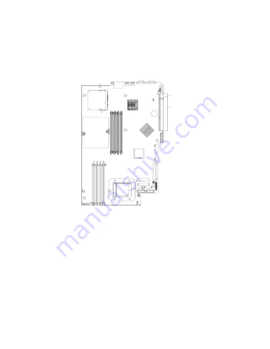
Determine


which


PCI-X


slot


you


will


use


for


the


adapter.


PCI-X slot 2 (PCIX2)

PCI-X slot 1 (PCIX1)


16


326


Type


8848:


Option


Installation


Guide

Summary of Contents for totalstorage 326

Page 1: ...326 Type 8848 Option Installation Guide ERserver...

Page 2: ......

Page 3: ...326 Type 8848 Option Installation Guide ERserver...

Page 4: ...general information in Notices on page 37 First Edition September 2004 Copyright International Business Machines Corporation 2004 All rights reserved US Government Users Restricted Rights Use duplicat...

Page 5: ...ule 22 Installing an additional microprocessor 24 Replacing the battery 28 Replacing a fan assembly 30 Completing the installation 33 Connecting the cables 33 Updating the server configuration 34 Chap...

Page 6: ...Power cords 42 Index 45 iv 326 Type 8848 Option Installation Guide...

Page 7: ...alleert eerst de veiligheidsvoorschriften Ennen kuin asennat t m n tuotteen lue turvaohjeet kohdasta Safety Information Avant d installer ce produit lisez les consignes de s curit Vor der Installation...

Page 8: ...Antes de instalar este producto lea la informaci n de seguridad L s s kerhetsinformationen innan du installerar den h r produkten vi 326 Type 8848 Option Installation Guide...

Page 9: ...r reconfiguration of this product during an electrical storm v Connect all power cords to a properly wired and grounded electrical outlet v Connect to properly wired outlets any equipment that will be...

Page 10: ...a lithium battery replace it only with the same module type made by the same manufacturer The battery contains lithium and can explode if not properly used handled or disposed of Do not v Throw or im...

Page 11: ...he device v Use of controls or adjustments or performance of procedures other than those specified herein might result in hazardous radiation exposure DANGER Some laser products contain an embedded Cl...

Page 12: ...tton on the device and the power switch on the power supply do not turn off the electrical current supplied to the device The device also might have more than one power cord To remove all electrical c...

Page 13: ...ices 82 kg 180 lb WARNING Handling the cord on this product or cords associated with accessories sold with this product will expose you to lead a chemical known to the State of California to cause can...

Page 14: ...xii 326 Type 8848 Option Installation Guide...

Page 15: ...ons This printed document contains instructions for installing the server in a rack v Hardware Maintenance Manual and Troubleshooting Guide This document is in PDF on the IBM Eserver Documentation CD...

Page 16: ...help you avoid inconvenient or problem situations v Attention These notices indicate potential damage to programs devices or data An attention notice is placed just before the instruction or situation...

Page 17: ...n hot swap hard disk drive model is also available Note The illustrations in this document might differ slightly from your hardware Microprocessor heat sink Microprocessor Dual inline memory module DI...

Page 18: ...or J16 Remote Supervisor Adapter II JMGT1 Secondary IDE IDE2 SCSI backplane signal SCSI1 System board power J10 SCSI backplane power J12 Front panel signal J13 System board power J11 Serial ATA connec...

Page 19: ...n the illustration are reserved See the section about recovering the basic input output system BIOS code in the Hardware Maintenance Manual and Troubleshooting Guide on the IBM Eserver Documentation C...

Page 20: ...ollowing illustration shows the external input output connectors ports on the system board Ethernet ports Dual JLAN1 Serial port 2 COM2 Serial port 1 COM1 Video port JVGA1 USB ports USB2 and USB1 6 32...

Page 21: ...tation CD Error Power LED J20 SCSI LED header J19 Fan 1 error LED DLED2 Fan 2 error LED DLED4 Microprocessor 2 error LED DLED14 Fan 3 error LED DLED6 Fan 4 error LED DLED8 Fan 5 error LED DLED10 Micro...

Page 22: ...on the system board for user installable options Microprocessor 1 U1 Microprocessor 2 U2 PCI X slot 2 PCIX2 PCI X slot 1 PCIX1 Remote Supervisor Adapter II JMGT1 Battery BAT1 Note The VRMs for the mic...

Page 23: ...ructions that come with optional adapters v You have replaced a failed fan as soon as possible Handling static sensitive devices Attention Static electricity can damage the server and other electronic...

Page 24: ...s restored v If the server is connected to an Advanced System Management interconnect network that contains at least one server with an optional Remote Supervisor Adapter II installed the server can b...

Page 25: ...the server v If the server is connected to an Advanced System Management interconnect network that contains at least one server with an optional Remote Supervisor Adapter II installed the server can...

Page 26: ...l retention tabs on the top right side and bottom of the server and pull the bezel directly away from the server Installing an adapter The following notes describe the types of adapters that your serv...

Page 27: ...SATA devices Note To change the boot precedence for PCI and PCI X devices you must disable the devices through the Configuration Setup Utility program Start the Configuration Setup Utility program an...

Page 28: ...illustration shows the cable routing if you are installing the RAID adapter in PCI X slot 1 See the documentation that comes with the RAID adapter for any additional cabling instructions That documen...

Page 29: ...connector on the rear edge of the adapter to the Remote Supervisor Adapter II connector JMGT1 on the system board For details about installing a Remote Supervisor Adapter II see the documentation tha...

Page 30: ...d all attached peripheral devices Disconnect all power cords then disconnect all external signal cables from the server 3 Remove the server from the rack then remove the server cover see Removing the...

Page 31: ...edge connectors on the adapter Ensure that the adapter is completely and correctly seated in the slot Incomplete insertion might cause damage to the system board or to the adapter 6 Remove the expansi...

Page 32: ...ward the server until it snaps into place to secure the adapter in the adapter slot 11 Connect any internal cables to the adapter See the instructions that come with the adapter for details Attention...

Page 33: ...swap drives Note The drive in bay 1 is assigned SCSI ID 0 the drive in bay 2 is assigned SCSI ID 1 v A non hot swap hard disk drive does not require a backplane or tray and it does not have indicator...

Page 34: ...e tray handle in open position Filler panel Drive bay 1 Drive bay 2 1 Read the safety information beginning on page v and Installation guidelines on page 9 2 Remove the filler panel from the applicabl...

Page 35: ...abs and pull the bezel directly away from the server Notes a If you have only one non hot swap hard disk drive install it in the right hand bay bay 2 with a jumper installed in the cable selection ena...

Page 36: ...s 1 1 and 2 2 3 and 4 v To optimize system performance in a dual microprocessor configuration install DIMMs in the following sequence DIMM pair DIMM slots 1 1 and 2 2 7 and 8 3 3 and 4 4 5 and 6 v The...

Page 37: ...11 Attention To avoid breaking the retaining clips or damaging the DIMM connectors open and close the clips gently 4 Open the retaining clip on each end of the DIMM connector 5 Touch the static protec...

Page 38: ...herwise go to Completing the installation on page 33 Installing an additional microprocessor The following notes describe the type of microprocessor that your server supports and other information tha...

Page 39: ...he ServerProven list at http www ibm com pc us compat for a list of microprocessors that are supported by the server Complete the following steps to install a microprocessor 1 Read the safety informat...

Page 40: ...damages its heat conducting capability and exposes the new microprocessor to overheating a Remove the heat sink from its package and remove the cover from the bottom of the heat sink b Make sure that...

Page 41: ...oprocessor socket Heat sink Heat sink retention module Captive screws 8 If you have other options to install install them now Otherwise continue with Completing the installation on page 33 Chapter 2 I...

Page 42: ...ery contains lithium and can explode if not properly used handled or disposed of Do not v Throw or immerse into water v Heat to more than 100 C 212 F v Repair or disassemble Dispose of the battery as...

Page 43: ...its housing b Use one finger to slide the battery up and out from its socket The spring mechanism will push the battery out toward you as you slide it from the socket 7 Insert the new battery a Hold...

Page 44: ...Installation guidelines on page 9 2 Turn off the server and all attached peripheral devices Disconnect all power cords then disconnect all external signal cables from the server 3 Remove the server fr...

Page 45: ...ver b Fans 2 4 and 5 are positioned so that the fan cable exits from the fan near the top of the server c Fan 3 is positioned so that the fan cable exits from the fan near the bottom of the server a 1...

Page 46: ...then through and around the heat sink duct as shown in the following illustration Heat sink duct b The cables for Fans 3 4 and 5 are routed up and then over to the appropriate connectors on the syste...

Page 47: ...below hard disk drive bay 1 5 Install the server in the rack For details see the Rack Installation Instructions that come with the server Note Depending on the options that you installed after cabling...

Page 48: ...on CD Updating the server configuration When you start the server for the first time after you add or remove an internal option or an external SCSI device you might see a message telling you that the...

Page 49: ...of the server Power cord connector Serial connector Video connector USB connectors Gigabit Ethernet 2 connector LAN2 Gigabit Ethernet 1 connector LAN1 The following sections describe these connectors...

Page 50: ...Use a Universal Serial Bus USB connector to connect a USB device USB technology transfers data at up to 12 Mb per second Mbps with a maximum of 127 devices and a maximum signal distance of 5 meters 16...

Page 51: ...Y OF ANY KIND EITHER EXPRESS OR IMPLIED INCLUDING BUT NOT LIMITED TO THE IMPLIED WARRANTIES OF NON INFRINGEMENT MERCHANTABILITY OR FITNESS FOR A PARTICULAR PURPOSE Some states do not allow disclaimer...

Page 52: ...orporation in the United States other countries or both UNIX is a registered trademark of The Open Group in the United States and other countries Java and all Java based trademarks and logos are trade...

Page 53: ...include user manuals or all program functionality Product recycling and disposal This unit contains materials such as circuit boards cables electromagnetic compatibility gaskets and connectors which...

Page 54: ...tors or by unauthorized changes or modifications to this equipment Unauthorized changes or modifications could void the user s authority to operate the equipment This device complies with Part 15 of t...

Page 55: ...has been tested and found to comply with the limits for Class A Information Technology Equipment according to CISPR 22 European Standard EN 55022 The limits for Class A equipment were derived for comm...

Page 56: ...cord part number Used in these countries and regions 02K0546 China 13F9940 Australia Fiji Kiribati Nauru New Zealand Papua New Guinea 13F9979 Afghanistan Albania Algeria Andorra Angola Armenia Austria...

Page 57: ...s Barbados Belize Bermuda Bolivia Brazil Caicos Islands Canada Cayman Islands Costa Rica Colombia Cuba Dominican Republic Ecuador El Salvador Guam Guatemala Haiti Honduras Jamaica Japan Mexico Microne...

Page 58: ...44 326 Type 8848 Option Installation Guide...

Page 59: ...drive 4 Ethernet 36 external 6 35 integrated drive electronics IDE 4 internal cable 4 memory 8 microprocessor 8 power 4 serial 36 small computer system interface SCSI 4 connectors continued system boa...

Page 60: ...et 36 port continued serial 36 Universal Serial Bus 36 video 36 power connectors 4 power cords 42 R RAID adapter cabling 14 installing 13 rear connectors 35 recovering the BIOS code 5 redundant array...

Page 61: ...Universal Serial Bus USB 36 updating the BIOS code 25 USB connectors 6 35 36 requirements 34 V video connector 6 36 W Web site IBM support 25 server compatibility information 9 Index 47...

Page 62: ...48 326 Type 8848 Option Installation Guide...

Page 63: ......

Page 64: ...Part Number 25K8176 Printed in USA 1P P N 25K8176...

Reviews: