

Set the switch password
Your switch ships with the default password:
password
. Change the password of your switch and keep the new password
in a secure location for reference. Write your password here if needed: _______________________________________
1.
Enter your password in the
Set Parameters
screen and follow the onscreen prompts.
2.
Enter a new name for the switch at this time, if desired. Accept the displayed date and time and click
Next
.
Configuring the zones and performing device selection
1.
Select
Typical Zoning
on the
Zone Configuration
screen and click
Next
.
Typical Zoning is the default zone configuration. See the
EZSwitchSetup Administrator’s Guide
for more information
on zone configuration.
2.
Enter the number and types of devices that you are connecting to the switch on the
Device Selection
screen.
EZSwitchSetup uses these values to automatically configure the ports on your switch for the devices that you are
connecting.
Connecting devices
The
Connect Devices
screen displays a graphical representation of the switch with the device connections based on the
information that you entered when you configured zones and performed device selection. The
Connect Devices
screen
will show all physical connections as missing until you connect the devices that you specified.
1.
Install the SFP transceivers in the Fibre Channel ports on the switch to match the ports shown onscreen.
a.
Remove any protector plugs from the SFP transceivers you are going to use, and position and insert
each SFP transceivers as required (right side up in the top row of ports and upside down in the bottom
row of ports). Push the SFP until it is firmly seated.
b.
Close the latching bale. Repeat for the other ports.
2.
Connect Fibre Channel cables from the switch (shown below) to your host and storage devices (not shown).
Make the physical connections to match the connections on the
Device Connection
screen.
3.
The
Finish screen
will display this message: “Congratulations—you’ve successfully completed the setup!”
4.
Click
Finish
to exit setup.
You are now ready to configure the storage component of the SAN using the documentation that came
with the storage server(s).
5
6
7
4-
0
1
!
1a
!
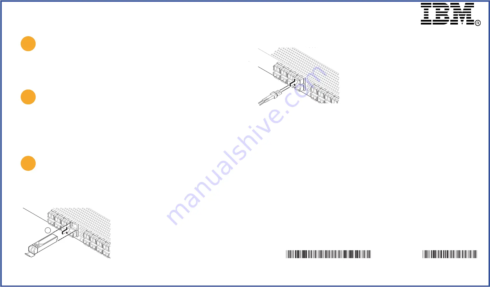
a.
Remove plastic protector caps from the Fibre Channel
cable ends (if there are any), and position the cable
connector so that it is oriented correctly.
b.
Insert the cable connector into the SFP until it is firmly
seated and the latching mechanism clicks.
c.
The
Device Connection screen
shows missing, valid, and
invalid connections as you cable the switch. Note that it
can take up to 15 seconds for the connection to display as
a valid connection. Verify that the connections are all
green and click Ne
Next.
GA32-0587-01
45W8151
© Copyright International Business Machines Corporation 2008, 2010. All rights reserved. US Government Users Restricted Rights –
Use, duplication or disclosure restricted by GSA ADP Schedule Contract with IBM Corp.
© 2008-2010 Brocade Communications Systems, Inc. All Rights Reserved.
Printed in USA
IBM, the IBM logo, and ibm.com are trademarks or registered trademarks of International Business Machines Corporation in the
United States, other countries, or both. A complete and current list of other IBM trademarks is available on the Web at
www.ibm.com/legal/


