IBM SurePOS 500 Technical Reference Download Page 34

SurePOS 500 4846-XX5 Technical Reference 

Page 34 of 63 

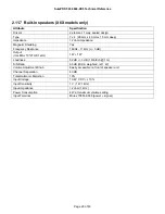
3.13  Vital Product Data 

Vital Product Data (VPD) is the IBM-specific information about a system.  The data includes values such as machine 
type, model, serial number, BIOS/Flash revision, system board unique ID, etc.  VPD is accessed through SMBIOS, as 
defined in the SMBIOS specification. 

3.13.1  VPD Layout in SMBIOS 

This section describes the traditional VPD.  Refer to the SMBIOS specification for methods of accessing these fields. 
 

Data field 

SMBIOS record Type and Field 

Data type  Field length 

Type 0 “BIOS Version” 

ASCII 
string 

BIOS level 

Example: X6KT100 


Type 1 “Product name” and “Version” 

ASCII 
string 

7  

Machine 
type/model 

Example: 4846545 
The machine type/model does not have dashes or spaces in SMBIOS 

System serial 
number 

Type 1 “Serial Number” 

ASCII 
string 

Product Family 

Type 1 “Family”, Type 11 

ASCII 
string 

11 

Type 1 “UUID”, offset 0Ah 
 

hex 6 

LAN MAC 
Address 

Usage: The LAN MAC address can be parsed from the Type 01 “UUID” field, offset 10 (0Ah).  
For example, if the UUID is 40 3E 4C 58 76 7B DA 11 A4 29 00 14 5E 14 00 15, the MAC 
address is 00 14 5E 14 00 15. 
 

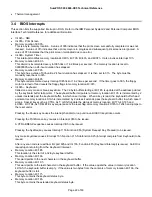
3.13.2  SMBIOS Type 11 Structure Layout 

The format of the SMBIOS Type 11 Structure for OEM strings is as follows: 

Offset Name 

Length Value  Description 

00h 

Type 

1 byte 

0Bh 

OEM strings structure indicator 

01h 

Length 

1 byte 

05h 

Length of structure 

02h Handle 

bytes 

varies 


04h 

Count 

1 byte 

varies 

Number of strings in this structure 

05h 

Product Family 
String 

11 bytes 

ASCII 
string 

“SurePOS 500” 

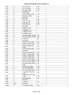
3.13.3  VPD using Int 15h 

;Get pointer to VPD block 
 mov 

ax, 

0d207h 

 int 

15h 

 
;ES:DI now points to the following structure: 
vpdDataStruc  STRUC 
 header 

  DW 

55aah 

 vpdSignature 

 DB 

'VPD' 

 vpdLength 

 DB 

48 

 reserved  DB 


dup(20h) 

 buildID 

  DB 


dup(20h) 

 boxSerial 

 DB 


dup(20h) 

 uniqueID  DB 

11 

dup(20H) 

 machineType 

 DB 


dup(20h) 

 vpdChecksum 

 DB 

vpdDataStruc  ENDS


Summary of Contents for SurePOS 500

Page 1: ...SurePOS 500 4846 XX5 Technical Reference Page 1 of 63 SurePOS 500 4846 545 565 Technical Reference Version 1 1...

Page 2: ...SurePOS 500 4846 XX5 Technical Reference Page 2 of 63 Change History Version Date Change Description 1 0 2 16 07 Initial Release...

Page 3: ...on 15 2 9 1 Block Diagram 15 2 10 Logic 16 2 11 Component specifications 17 2 11 1 4GB Modular Flash Drive 17 2 11 2 Hard Disk Drive 17 2 11 3 LCD 18 2 11 4 Magnetic Stripe Reader 18 2 11 5 Integrated...

Page 4: ...gonomics and accessibility 36 6 0 External Ports 37 6 1 Port Listing 37 6 2 Port Power Ratings 37 6 3 Connector Pinouts 38 6 3 1 Customer Display Connector 38 6 3 2 MSR connector 38 6 3 3 USB Plus Pow...

Page 5: ...including powered 12V and 24V USB 2 0 ports standard A wide range of optional features including receipt printers displays and trays to keep the counter neat 1 2 Models Model Base Admin Model WEPOS Bu...

Page 6: ...nding Integration Trays Security Power On Password Bolt down Tray Mounting 1 4 Related Publications SurePOS 500 Series Planning Installation and Operation Guide for Models 545 and 565 GA27 4365 This g...

Page 7: ...acy mode Up to 32MB UMA Multi Monitor True multi monitor with dual video adapter True multi monitor w Cedar adapter No 2nd display option Touch Screen Technology IBM enhanced ELO IR ELO IR Carroll Tou...

Page 8: ...Common with 4840 3 Track MSR New P N to 4846 JUCC MSR New P N to 4846 Counter Integration Tray SST New P N new fillers added Standard CD Integration Tray 4610 kybd New P N new fillers added Compact CD...

Page 9: ...pplication Driver Notes PC DOS 2000 Hardware direct interface only Windows 2000 XP Windows Embedded Point of Service WEPOS Power management via ACPI Notes Only DOS full screen mode supported due to to...

Page 10: ...up wake on daily alarm This feature enables the system to turn on at the same time every day You can enable power up wake on daily alarm by enabling Wake on Alarm in the CMOS Setup Utility program RMA...

Page 11: ...s Distributed 2x20 display 0 5 kg 1 2 lbs Distributed APA display 0 7 kg 1 6 lbs MSR three track or JUCC 0 16 kg 0 41 lbs 2 8 1 3 Dimensions with Trays Measurement A see figure below Measurement B see...

Page 12: ...ry contact button Under LCD chin Decreases brightness by 1 step 2 8 3 Visual Indicators Function Color Location State Power Green Front bezel Off System Off Blinking Standby during POST On Operational...

Page 13: ...urePOS 500 4846 XX5 Technical Reference Page 13 of 63 2 8 4 Connector Controls Identifier Identifier Function A MSR B C USB 2 0 D Tablet attachment E Touch Ring F USB 2 0 G H Brightness up down button...

Page 14: ...46 XX5 Technical Reference Page 14 of 63 I Power control J RS232 K External Display RS232 L Analog Video M Keyboard N Mouse O P Cash Drawer Q Ethernet R 24V USB 2 0 Plus Power S 12V USB 2 0 Plus Power...

Page 15: ...SurePOS 500 4846 XX5 Technical Reference Page 15 of 63 2 9 Product Description 2 9 1 Block Diagram...

Page 16: ...2 0 GB s Link to South Bridge Digital Display Support SDVO output 200Mhz dot clock Scaling using Chrontel 7308 LVDS scaler Analog Display Support 400Mhz Integrated 24 bit RAMDAC Up to 2047x1536 85Hz r...

Page 17: ...t PCI 33 Touch ELO based Infra redesign RS232 interface to touch mouse emulation Flashable firmware via USB Touch Specifications Attribute Specification Technology Modified ELO Infra red Calibration N...

Page 18: ...811 Tracks 1 2 3 capability Enable Disable Carriage Return Enable Disable Sentinels Programmable Sentinels Individually selectable Tracks Flashable firmware For details on configuring the MSR go to th...

Page 19: ...uage requirements It attaches to the 15 Pin Powered serial port which provides power and signaling Attribute Specification Technology Vacuum Fluorescent Brightness 300 cd m2 Format dot 160 x 40 Active...

Page 20: ...Frequency Response 160Hz 11 kHz 3 dB Output rms EIAJ 10 THD 1kHz 1W 1 W Loudness 82 dB 3 dB 1 Watt ch 1 m S N Ratio 65 dB IEC A weighted ref 1 W Volume Adjustment Knob Easily accessible on front of sp...

Page 21: ...PCI BIOS Specification Revision 2 3 March 29 2002 El Torito Bootable CD ROM Format Specification v1 0 January 25 1995 Preboot Execution Environment PXE Specification Version 2 1 Advanced Power Manage...

Page 22: ...nter at memory location 40 1Ch is incremented by 2 unless it extends past the keyboard buffer in which case it wraps When a key is read the keyboard buffer head pointer at memory location 40 1Ah is in...

Page 23: ...eyboard Services Int 1Ah System Timer Services PCI BIOS Int 1Bh CTRL Break Handler Int 1Ch Periodic Timer Interrupt Int 1Dh Video Parameter Table Set by the video BIOS Int 1Eh Floppy Diskette Drive Pa...

Page 24: ...pt Using It Comments 00h 2 COM1 base address 14h motherboard UART1 I O address 02h 2 COM2 base address 14h motherboard UART2 I O address 04h 2 COM3 base address 14h motherboard UART5 I O address 06h 2...

Page 25: ...10h 89h 2 Reserved 8Bh 1 Floppy media control 13h 8Ch 1 HDD Controller status 13h 8Dh 1 HDD Controller error status 13h 8Eh 1 HDD Interrupt control 13h 8Fh 1 Reserved 90h 1 Floppy 0 media status 13h...

Page 26: ...Conventional DOS memory size may decrease if booted via LAN 639 KB 9FC00 9FFFF 1 KB EBDA Extended BIOS Data moveable by Himem memory managers 640 767 KB A0000 BFFFF 128 KB Legacy Video Buffer 768 831...

Page 27: ...J45 Rear Tailgate BDA COM2 2F8 3 UART3 COM3 Available to user RJ45 Rear Tailgate COM6 2E0 11 Distributed VFD connection DB15 F Rear Tailgate Integrated VFD connection Custom Tower Top BDA COM4 Only on...

Page 28: ...A 9 x 16 80 x 25 28 31 5 70 256 04h 320 x 200 4 Graph All 8 x 8 40 x 25 25 31 5 70 256 320 x 200 4 gray Graph CGA 8 x 8 40 x 25 25 31 5 70 256 320 x 200 4 gray EGA 8 x 8 40 x 25 25 31 5 70 256 05h 320...

Page 29: ...24 x 768 256 8 bpp Graph XVGA 60 1 1024 x 768 256 8 bpp Graph XVGA 75 1 105h 1024 x 768 256 8 bpp Graph XVGA 85 1 1280 x 1024 256 8 bpp Graph SXGA 60 2 1280 x 1024 256 8 bpp Graph SXGA 75 2 107h 1280...

Page 30: ...only one display device Twin A type of display configuration that supports two display devices each of which has the same content resolution and timings Also referred to as Simultaneous mode Clone A...

Page 31: ...Windows operating system LCD size Available video resolutions for onboard LCD 12 in 640 x 480 720 x 480 800 x 600 15 in 640 x 480 720 x 480 800 x 600 960 x 540 1024 x 768 17 in 640 x 480 720 x 480 80...

Page 32: ...g No Global Suspend Save to disk or RAM State No Power on by keyboard No Battery support No 3 11 2 ACPI Function Supported From State Comments Global Standby Yes power button inactivity timer Wake on...

Page 33: ...me Version Serial number Wake up Type Base Board or Module Information Type 2 System Enclosure Type 3 Processor information Type 4 Cache Information Type 7 On Board Devices Information Type 10 Physica...

Page 34: ...t Family Type 1 Family Type 11 ASCII string 11 Type 1 UUID offset 0Ah hex 6 LAN MAC Address Usage The LAN MAC address can be parsed from the Type 01 UUID field offset 10 0Ah For example if the UUID is...

Page 35: ...170W Input Voltage 100 127 200 240 VAC nominal 50 or 60 Hz 3 Hz Sinusoidal trapezoidal or square wave inputs kVA 0 3 AC Input Connector Cable IEC 320 C14 unshielded right angle type Leakage current 3...

Page 36: ...S EN 50024 1998 EN61000 4 3 Criteria A Electrical Fast Transient Power Line Transient EFT PLT EN 50024 1998 EN61000 4 4 Criteria B Near Field Phenomena MPRII Power Line Disturbance Ring EN50024 1998 E...

Page 37: ...gate USB 3 USB 2 0 USB Type A Rear Tailgate USB 4 USB 2 0 USB Type A Rear Tailgate USB 5 USB 2 0 USB Type A Tablet USB 6 USB 2 0 USB Type A Tablet USB 7 USB 2 0 USB Type A Tablet Chin near brightness...

Page 38: ...Dist_VFD present 4 DTR data terminal ready 12 DSR data set ready 5 Ground 13 RTS request to send 6 Ground 14 CTS clear to send 7 5 V dc Main 15 RI ring indicate 8 12 V dc 5 3 2 MSR connector Pin Conne...

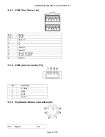
Page 39: ...5 3 3 USB Plus Power 2x Pin Signal Shell Shield 1 VBus 5V 2 D 3 D 4 Ground 5 Ground 6 Vplus 12V or 24V 7 Vplus 12 or 24V 8 Ground 5 3 4 USB port connector 7x Pin Connector 1 5V VBus 2 Data 3 Data 4 G...

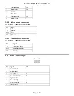
Page 40: ...present on X6X models Pin Signal Tip Signal Ring 5 V Base Ground 5 3 7 Headphone Connector This connector is only present on X6X models Pin Signal Tip Left channel audio Ring Right channel audio Base...

Page 41: ...O 2 TxD O 3 RxD I 4 Ground 5 Ground 6 RxD I 7 Ground 8 Ground 5 4 2 External video connector Pin Connector 1 Red 2 Green 3 Blue 4 Monitor ID2 not used 5 Ground 6 Red ground 7 Green ground 8 Blue grou...

Page 42: ...Connector 1 Ground 2 Sense 3 Open 4 24V 5 4 4 Internal Customer Display Pin Connector 1 5V Main 2 Transmit Data 3 Int VFD Present 4 Ground 5 4 5 RJ45 to RS232 Cable Signal Pin number RJ45 End Pin num...

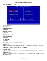
Page 43: ...all configurable items in CMOS Setup Set Password Sets the numeric password used for the Security Option item using a keyboard or on screen numpad See section x Select Enter at the Enter Password pro...

Page 44: ...on Shows the current BIOS revision BIOS Date Shows the BIOS revision date LAN MAC Address Shows the onboard NIC MAC Address Machine Type Model Shows the Machine Type and Model Machine Serial Number Sh...

Page 45: ...on this menu is not recommended 6 3 Advanced BIOS Features CPU Feature Select Enter to view the sub menu See section Hard Disk Boot Priority Shows the Hard Disk devices that will be booted if Hard Di...

Page 46: ...ng This will decrease the time needed to boot the system Default Enabled Options Disabled Enabled 6 3 1 First Boot Device The system will attempt to boot from the specified device category before tryi...

Page 47: ...y all booting all device categories if the first through fourth boot devices fail Default Disabled Options Disabled Enabled Alternate Boot Sequence Specifies whether a Magic Packet TM powering on the...

Page 48: ...oots or only when entering CMOS Setup Select Setup to require a password before entering the CMOS Setup Utility Select System to require a password before entering CMOS setup or before booting from on...

Page 49: ...ices include USB Memory Keys Hard Disk drives and the Modular Flash Drive Select an item and use PageUp and PageDown to adjust the boot priority Only the first item in the list is booted as a Hard Dis...

Page 50: ...turn 0 See the following article for more information http technet2 microsoft com WindowsServer en Library b0de1052 4101 44c3 a294 4da1bd1ef2271033 mspx mfr true Default Enabled Options Enabled Disabl...

Page 51: ...he default value is recommended If modified ensure the selected IRQ does not conflict with other ports as values cannot be shared Default 4 Options 3 4 5 6 7 11 Serial Port B I O Selects the I O addre...

Page 52: ...ault 3E8h Options Disabled 2E0h 2E8h 2F8h 2D8h 3E8h 3F8h MSR IRQ Selects the IRQ used for the MSR if MSR Communication Mode is set to RS 232 If the MSR is configured for Keyboard Wedge mode the select...

Page 53: ...s available as a fourth standard serial port Port D is a 15 pin D shell connector that includes power as well as the serial port signals The system communicates with the displays in a unidirectional m...

Page 54: ...nfigured Serial Port C I O Selects the I O address used for Serial Port C Using the default value is recommended If modified ensure the selected I O address does not conflict with other ports as value...

Page 55: ...e EHCI USB 2 0 controller If disabled the USB ports will operate as 1 X ports only Default Enabled Options Enabled Disabled USB Keyboard Support Enables or disables USB keyboard support in non USB awa...

Page 56: ...beeps are always enabled from the motherboard beeper Default Enabled Options Disabled Enabled Typematic Rate Setting If disabled keystrokes repeat at a rate determined by the keyboard controller If e...

Page 57: ...nd Mode and HDD Power Down timeout values User Define allows selection of the Suspend Mode and HDD Power Down timeouts This item does not apply to ACPI environments such as Windows Default User Define...

Page 58: ...ctivity will cause the hard disk to spin back up This option is only available if Power Management is set to User Define This item does not apply to ACPI environments such as Windows Default Disabled...

Page 59: ...o wake the system via Ring Indicate Ports A C can be jumpered to tie DSR pin1 to Ring Indicate if required Default Disabled Options Disabled Enabled Wake on Alarm If enabled the allows the system to w...

Page 60: ...Extended System Configuration Data ESCD if the operating system cannot boot The option automatically returns to Disabled on the next boot Default Disabled Options Disabled Enabled Resources Controlle...

Page 61: ...for information only and cannot be configured 6 9 PC Health Status Primary BIOS Status Shows the status of the primary boot flash ROM If the primary BIOS becomes corrupted due to power loss during a...

Page 62: ...RPMs This item is for information only and cannot be configured 6 9 1 Thermal Profile Thermal Profile Selects the thermal management profile best suited to your environment Quiet allows less fan nois...

Page 63: ...SurePOS 500 4846 XX5 Technical Reference Page 63 of 63 END OF DOCUMENT...

Reviews: