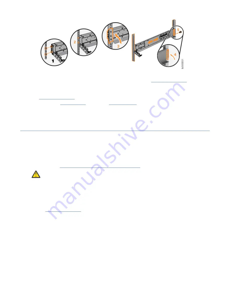
Figure 15. Closing the hinge brackets
9. Secure the rear bracket to the rail with a black M5 screw (step 5 in Figure 15 on page 19).
10. On the front of the rail, press the two bracket pins into the holes in the rack flanges.
11. Close the front hinge bracket to secure the rail to the rack cabinet flange.
Figure 15 on page 19 shows an example.
12. Repeat step “2” on page 16 through step “11” on page 19 to secure the opposite rail to the rack
cabinet.
13. Repeat the procedure to install rails for each additional control enclosure.
Installing enclosures
Following your enclosure location plan, install the control enclosure (and optionally, one or more
expansion enclosures).
About this task
Note: For NEBS-compliant installations, more requirements are placed on the rack into which the support
rails and enclosures are to be installed. Before you proceed, ensure that the rack meets the requirements
that are listed in “NEBS-compliant earth connection” on page 15.
CAUTION: Load the rack from the bottom up to ensure rack stability. Empty the rack from the top
down.
Procedure
To install an enclosure, complete the following steps.
1. On either side of the drive assemblies, remove the enclosure end caps by grasping the handle and
pulling the bottom of the end cap free, then clearing the tab on the top of the enclosure.
(See Figure 16 on page 20.)
Chapter 2. Installing the system hardware 19
Summary of Contents for Storwize V5000 Gen 2 Series
Page 1: ...IBM Storwize V5000 Gen2 Quick Installation Guide IBM...
Page 5: ...Index 149 v...
Page 6: ...vi...
Page 156: ...130 Storwize V5000 Gen2 Quick Installation Guide...
Page 164: ...138 Storwize V5000 Gen2 Quick Installation Guide...
Page 166: ...140 Storwize V5000 Gen2 Quick Installation Guide...
Page 168: ...142 Storwize V5000 Gen2 Quick Installation Guide...
Page 177: ......
Page 178: ...IBM...


