background image

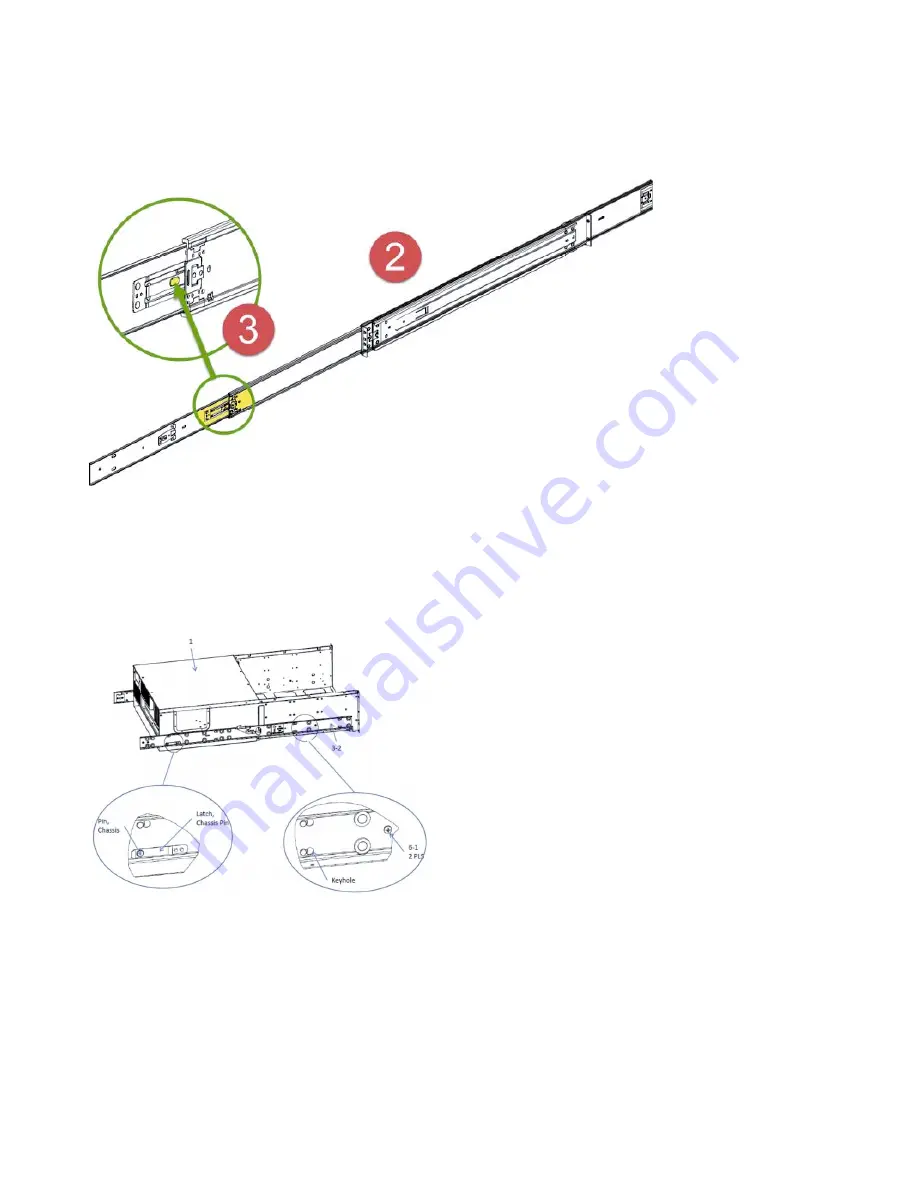
Disconnect chassis section slide assembly

Refer to the following figure to open the chassis section slide assembly.

Install the chassis slide rails to the appliance

1.

With the heads of the locating pins protruding through the set of keyhole openings in the chassis
section assembly, pull the slide toward the front of the chassis until the screw holes line up, as shown
in the following figure.

2.

Attach the slide by inserting two M4 screws through the holes in the slide and securing them to the
chassis.

3.

Repeat these steps for the other side of the chassis.

Attach the rack slide rails to the rack

1.

Define the "U" spacing and attach the slide, as shown in the following figure.

Figure 3. Disconnecting the chassis slide assembly

Figure 4. Install the chassis slide rails to the appliance

8

IBM Cloud Object Storage System

: Slicestor 2448 Appliance Manual 3409-S01/3401-S01/3403-S01

Summary of Contents for Slicestor 2448

Page 1: ...IBM Cloud Object Storage System Version 3 13 1 Slicestor 2448 Appliance Manual 3409 S01 3401 S01 3403 S01 IBM...

Page 2: ...ental notices v The information in the IBM Environmental Notices and User Guide provided on a DVD This edition applies to IBM Cloud Object Storage System Slicestor 2448 and is valid until replaced by...

Page 3: ...cifications and requirements 3 Appliance specifications 3 Requirements 3 Chapter 3 Install the appliance into a rack 5 Prepare for installation 5 Application installation 6 Chapter 4 Appliance physica...

Page 4: ...iv IBM Cloud Object Storage System Slicestor 2448 Appliance Manual 3409 S01 3401 S01 3403 S01...

Page 5: ...ach the rack rails to the rack 9 6 Unlock the rails 10 7 Rear of appliance 10 8 Front panel buttons and LEDs for the appliance 11 9 Rear panel I O ports for the appliance 12 10 System diagram 15 11 Re...

Page 6: ...vi IBM Cloud Object Storage System Slicestor 2448 Appliance Manual 3409 S01 3401 S01 3403 S01...

Page 7: ...power requirements for the appliance 3 3 Operating and non operating temperatures and humidity for the appliance 4 4 Cabling requirements for the appliance 4 5 Appliance location considerations 5 6 HD...

Page 8: ...viii IBM Cloud Object Storage System Slicestor 2448 Appliance Manual 3409 S01 3401 S01 3403 S01...

Page 9: ...drives prior to attempting this installation Only personnel proficient in working with computer hardware and disk drives should attempt to install this appliance v After all appliances have been inst...

Page 10: ...x IBM Cloud Object Storage System Slicestor 2448 Appliance Manual 3409 S01 3401 S01 3403 S01...

Page 11: ...a danger notice Numbers in parentheses refer to message numbers in the IBM Safety Notices publication G229 9054 which is included with your product CAUTION A caution notice indicates the presence of...

Page 12: ...xii IBM Cloud Object Storage System Slicestor 2448 Appliance Manual 3409 S01 3401 S01 3403 S01...

Page 13: ...Safety and environmental notices xiii...

Page 14: ...ronmental Notices http ibm co 1fBgWFI information includes statements on limitations product information product recycling and disposal battery information flat panel display refrigeration and water c...

Page 15: ...d decibels respectively 1 B 10 dB 4 Note Government regulations such as those prescribed by OSHA or European Community Directives may govern noise level exposure in the workplace and may apply to you...

Page 16: ...xvi IBM Cloud Object Storage System Slicestor 2448 Appliance Manual 3409 S01 3401 S01 3403 S01...

Page 17: ...formation For more information on the product or help with troubleshooting contact IBM Support at IBMCloudStorageSupport us ibm com or visit the Directory of worldwide contacts Copyright IBM Corp 2016...

Page 18: ...xviii IBM Cloud Object Storage System Slicestor 2448 Appliance Manual 3409 S01 3401 S01 3403 S01...

Page 19: ...eckties and unbuttoned shirt sleeves They can retain a charge even if you are wearing a wrist strap or could be pulled into a fan v After you access the inside of the appliance close the appliance and...

Page 20: ...components and printed circuit boards PCBs In general the following measures are sufficient to neutralize this difference before contact is made to protect equipment from ESD v Use a grounded wrist s...

Page 21: ...1 configuration Extra Networking Options The appliance can support other networking cards to provide extra Ethernet ports These ports are shown in the highlighted card slots on the rear of the applian...

Page 22: ...e of cord Do not use extension cords If extra power cords are needed contact IBM Support 1000BASE T Copper Cables Use high quality Category 5e or 5 CAT5e CAT5 copper cables Optical Fiber Cables Use IB...

Page 23: ...with the maximum rated ambient temperature TMRA for the appliance Sufficient airflow Mount the equipment into a rack so that the amount of airflow that is needed for safe operation is not compromised...

Page 24: ...n any way 3 Open the top of the box and inspect for damage 4 Remove all of the components from the packaging and inspect for damage 5 Arrange for assistance when lifting or installing the appliance in...

Page 25: ...TION Before lifting or transporting the server make sure the four side handles two on each side are securely screwed into the server Failure to do so can result in severe personal injury and server da...

Page 26: ...screw holes line up as shown in the following figure 2 Attach the slide by inserting two M4 screws through the holes in the slide and securing them to the chassis 3 Repeat these steps for the other s...

Page 27: ...ils 2 Continue to close until the side rails lock 3 After the server is partially inserted into the rack rails remove the server side handles 4 Place the handles back in the drive carriers and replace...

Page 28: ...the left of the center of the appliance and are next to each other Connect a standard Ethernet cable to the left Ethernet port 3 Press the power button that is on the bottom center of the appliance f...

Page 29: ...n Powers on or powers off the system Turning off system power with this button removes the main power but keeps standby power that is supplied to the system Therefore you must unplug the system before...

Page 30: ...marked 1 is lit the fan assembly 1 5 which consists of a single dual motor fan must be replaced See Replace the Fans for details 5 Power LED Shows green when power is on unlit when power is off 7 Glob...

Page 31: ...C card has two LEDs The Upper LED indicates link speed Blue 10G link Yellow 1G link and the bottom LED indicates Link Activity Link green Activity flashing green Onboard 1 GbE NIC LEDs Each of the two...

Page 32: ...14 IBM Cloud Object Storage System Slicestor 2448 Appliance Manual 3409 S01 3401 S01 3403 S01...

Page 33: ...are available v Data drives v Optical modules SFP QSFP See the Field Replaceable Units Reference Guide for a complete list of available data drives System diagram The following figures show the applia...

Page 34: ...ar loading OS drive 1 Log in to the device as localadmin 2 At the command prompt type poweroff 3 After the appliance is powered off remove the power cord and network cables from the back of the chassi...

Page 35: ...e USB flash drive dd if path ClevOS iso of dev drivename bs 1M 6 When copying is done remove the USB flash drive from the computer 7 Power down the device on which you want to install the OS v If the...

Page 36: ...es into the chassis until they are fully inserted and click into place 6 Press down on the latch of each drive until they lock in place 7 Replace the top cover 8 Restart the system Replace a power sup...

Page 37: ...ON and OK AC and DC LED green Power supply failure FAIL LED amber Power supply warning 1 Hz flashing amber Follow these steps to replace a failed power supply 1 Unplug the power cord CAUTION After yo...

Page 38: ...the fiber optic cable into the SFP QSFP module 7 Restart system and configure the network interface For more information see the Appliance Configuration Guide Battery removal and installation Battery...

Page 39: ...guidelines Battery installation To install an onboard battery follow these steps 1 Identify the battery s polarity The positive side must be facing up 2 Insert the battery into the battery holder Pus...

Page 40: ...22 IBM Cloud Object Storage System Slicestor 2448 Appliance Manual 3409 S01 3401 S01 3403 S01...

Page 41: ...CS information contact the IBM Intellectual Property Department in your country or send inquiries in writing to Intellectual Property Licensing Legal and Intellectual Property Law IBM Japan Ltd 19 21...

Page 42: ...ly All IBM prices shown are IBM s suggested retail prices are current and are subject to change without notice Dealer prices may vary This information is for planning purposes only The information her...

Page 43: ...torage Insight IBM Cloud Object Storage Manager IBM Cloud Object Storage Slicestor IBM Cloud Object Storage Standard IBM Cloud Object Storage System IBM Cloud Object Storage Vault SecureSlice and Slic...

Page 44: ...26 IBM Cloud Object Storage System Slicestor 2448 Appliance Manual 3409 S01 3401 S01 3403 S01...

Page 45: ......

Page 46: ...IBM Printed in USA...

Reviews: