background image

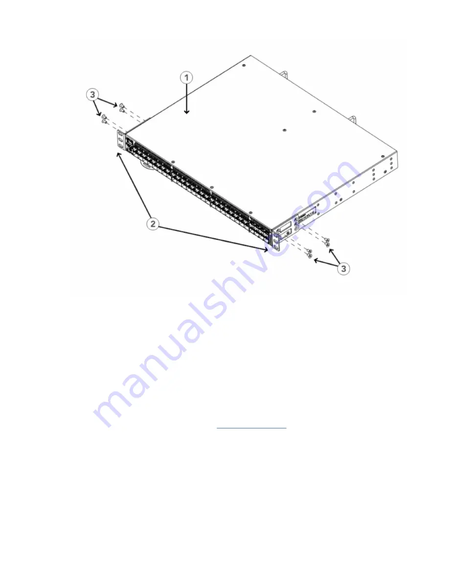
Figure 17. Attaching the front brackets

1 - The SAN64B-6 switch
2 - Front brackets, right and left
3 - Screws, 8-32 x 5/16-in., flathead Phillips

Attaching the front brackets to the rack

About this task
Complete the following steps to install the device in the rack.

Procedure

1. Position the device in the rack, as shown in (Figure 18 on page 29), providing temporary support

under the device until the rack kit is fully secured to the rack.

2. Attach the right front bracket to the right rack upright using two 10-32 x 5/8-in. panhead screws and

two retainer nuts. Use the upper and lower holes in the bracket.

3. Attach the left front bracket to the left rack upright using two 10-32 x 5/8-in. panhead screws and two

retainer nuts.

4. Use the upper and lower holes in the bracket. Tighten all the 10-32 x 5/8-in. screws to a torque of 25

in-lb. (29 cm-kg).

28  IBM Storage Networking SAN64B-6: SAN64B-6 Installation, Service, and User Guide

Summary of Contents for SAN64B-6

Page 1: ...IBM Storage Networking SAN64B 6 MTM Service information 8960 F64 F65 8960 N64 N65 Installation Service and User Guide IBM SC27 8965 02...

Page 2: ...re provided Before you use the information in this publication be sure to read the general information under Notices on page 89 Copyright Portions Copyright 2020 Broadcom Inc All Rights Reserved Copyr...

Page 3: ...n 19 rack xx Product recycling and disposal xxi About this document xxiii Product documentation xxiii Brocade documents xxiii IBM and Brocade product matrix xxiii Chapter 1 Introducing the SAN64B 6 1...

Page 4: ...Precautions specific to transceivers and cables 48 Cleaning the fiber optic connectors 48 Managing cables 48 Installing an SFP transceiver 49 Replacing an SFP transceiver 50 Installing a QSFP transce...

Page 5: ...assis 78 Chapter 9 Power supply and fan assembly 79 Removing the battery 79 Appendix A Product specifications 81 Notices 89 Trademarks 90 Homologation statement 90 Electronic emission notices 90 Feder...

Page 6: ...vi...

Page 7: ...ts to the rear of the device 20 11 Attaching the bracket extensions to the device 21 12 Positioning the device in the rack 22 13 Attaching the rear brackets to the extensions at the front of the devic...

Page 8: ...27 Replacing a 32 Gbps SFP optical transceiver 50 28 Installing a 32 Gbps QSFP transceiver in an upper port 51 29 Replacing a QSFP optical transceiver 52 30 SAN64B 6 Port Side LEDs 53 31 AC Power Sup...

Page 9: ...ameter selection for the US time zones 41 8 System power LED patterns during normal operation 54 9 System status LED patterns during normal operation 54 10 Management Port LED patterns during normal o...

Page 10: ...x...

Page 11: ...updates link on the product documentation CD that is shipped with this product You can also contact IBM within the United States at 1 800 IBMSERV 1 800 426 7378 For support outside the United States...

Page 12: ...re information about the commitment that IBM has to accessibility How to send your comments Your feedback is important in helping us provide the most accurate and high quality information If you have...

Page 13: ...These notices provide important tips guidance or advice Attention notices on page xix These notices indicate potential damage to programs devices or data Cautions on page xiii These statements indicat...

Page 14: ...olled by the authority responsible for the location CAUTION For the DC input circuit to the system make sure there is a 10 Amp circuit breaker maximum 60 VDC double pole on the input terminal block to...

Page 15: ...h the device to connect it to the power source DANGER Remove both power cords before servicing DANGER Disconnect the power cord from all power sources to completely remove power from the device DANGER...

Page 16: ...must keep the slot filler panel in place If you run the chassis with an uncovered slot the system will overheat CAUTION Do not install the device in an environment where the operating ambient tempera...

Page 17: ...have more than one power cord To reduce the risk of electric shock disconnect all power cords before servicing DANGER Remove both power cords before servicing DANGER Disconnect the power cord from all...

Page 18: ...ed to support the weight of the module which can fall and be damaged CAUTION To prevent damage to the chassis and components never attempt to lift the chassis using the fan or power supply handles The...

Page 19: ...tage present Voltages present constitute a shock hazard which can cause severe injury or death L004 CAUTION Hazardous moving parts nearby L008 Attention notices An attention notice indicates the possi...

Page 20: ...rack where the internal rack ambient temperatures will exceed the manufacturer s recommended ambient temperature for all your rack mounted devices Do not install a unit in a rack where the air flow i...

Page 21: ...position Ensure that there is no stabilizer bracket installed on the rack cabinet during movement Do not use a ramp inclined at more than 10 degrees Once the rack cabinet is in the new location do th...

Page 22: ...xxii IBM Storage Networking SAN64B 6 SAN64B 6 Installation Service and User Guide...

Page 23: ...can find information related to the software that supports the switch in the following documents on the CD ROM supplied with this product Brocade Fabric OS EZSwitchSetup Administrator s Guide Fabric O...

Page 24: ...AN512B 7 8961 Model F78 Brocade X6 4 Director IBM Storage Networking SAN256B 6 8961 Model F04 Brocade X6 8 Director IBM Storage Networking SAN512B 6 8961 Model F08 Brocade 6520 IBM System Networking S...

Page 25: ...10Gb s Note The port speed is determined by the maximum speed supported by the optical transceiver at the other end of the link 10 Gbps manually set capability on FC ports requires the optional 10 Gi...

Page 26: ...ng functionality by facilitating easier firmware upgrades and downloads of the system log files One external USB connector Two hot swappable redundant integrated power supply and fan assembly field re...

Page 27: ...r Ports 24 31 8 SFP FC four upper and four lower Ports 32 39 9 SFP FC four upper and four lower Ports 40 47 10 QSFP Port 0 FC Ports 48 51 11 QSFP Port 2 FC Ports 56 59 12 QSFP Port 3 FC Ports 60 63 13...

Page 28: ...wer Ports 32 39 9 SFP FC four upper and four lower Ports 40 47 10 QSFP Port 0 FC Ports 48 51 11 QSFP Port 2 FC Ports 56 59 12 QSFP Port 3 FC Ports 60 63 13 QSFP Port 1 FC Ports 52 55 14 SFP lower Port...

Page 29: ...es You can manage the device using any of the management options listed in the following table Table 2 Management options for the device Management tool Out of band support In band support Reference d...

Page 30: ...hernet or serial connection Native in band interface over HBA only Fabric OS Administrator s Guide Fabric OS Command Reference Network Advisor BNA BNA must be purchased separately Ethernet or serial c...

Page 31: ...ts Before installing the device be sure the following facilities requirements are met Table 3 Facility requirements Type Requirements Electrical Adequate supply circuit line fusing and wire size as sp...

Page 32: ...plet ed Unpack the switch Take an inventory of the hardware components included in your shipment Refer to Items included with the switch on page 10 Gather necessary components and required tools Revie...

Page 33: ...Attach a management station establish a serial connection and change the default passwords optional Refer to Establishing a first time serial connection on page 38 After completing this task log in to...

Page 34: ...show errdump Back up the configuration Use the interactive configupload command to back up the configuration Refer to Verifying correct operation on page 43 for more information Optional Power off the...

Page 35: ...versal Two Post Rack Kit to install 1U and 2U devices in a two post telecommunications Telco rack Note Review Precautions specific to mounting on page 11 before mounting the device Precautions specifi...

Page 36: ...the following instructions to install 1U and 2U devices in EIA racks that are from L 12 7 cm to 81 28 cm L 5 0 in to 32 0 in deep where L is the chassis depth using the Universal Four Post Rack Kit Yo...

Page 37: ...fic installation and facility requirements in the hardware installation guide for the device Hardware devices illustrated in these procedures are for reference only and may not depict the device that...

Page 38: ...Complete the following tasks to install the device in a four post rack 1 Attaching the front brackets 2 Attaching the bracket extensions to the device 3 Installing the device in the rack 4 Attaching...

Page 39: ...et for your rack depth 2 Position the right extension bracket along the side of the device as shown in Figure 6 on page 16 3 Insert four 8 32 x 5 16 in flathead screws through the vertically aligned h...

Page 40: ...the device until the rail kit is secured to the rack 2 Attach the right front bracket to the right front rack post using two 10 32 x 5 8 in panhead screws and two retainer nuts Use the upper and lower...

Page 41: ...ur rack Procedure 1 Select the proper length rear bracket for your rack depth 2 Slide the right rear bracket onto the right extension and attach to the extension by inserting four 6 32 x 1 4 in panhea...

Page 42: ...et to the right rear rack post using two 10 32 x 5 8 in panhead screws and two retainer nuts as shown in Figure 9 on page 19 Use the upper and lower holes in the bracket 2 Attach the left rear bracket...

Page 43: ...n the rack installation procedures show a 1U device but the instructions are the same for a 2U device The illustrations in the rack installation procedures are for reference only and may not show the...

Page 44: ...gure 10 on page 20 2 Insert four 8 32 x 5 16 in flathead screws through the vertically aligned holes in the bracket and then into the holes on the side of the device Use the upper and lower screw hole...

Page 45: ...he right extension along the side of the device as shown in Figure 11 on page 21 3 Attach the bracket using four 8 32 x 5 16 in flathead screws 4 Repeat step 1 and step 2 to attach the left front exte...

Page 46: ...25 in lb 29 cm kg Figure 12 Positioning the device in the rack 1 Screws 10 32 x 5 8 in panhead Phillips 2 Retainer nuts 10 32 Attaching the rear brackets to the extensions at the front of the device A...

Page 47: ...22 and step 3 on page 23 to attach the left rear bracket to the left extension 5 Adjust the brackets to the rack depth and tighten all the 6 32 x 1 4 in screws to a torque of 9 in lb 10 cm kg Figure 1...

Page 48: ...ch the right rear bracket to the right front rack post using two 10 32 x 5 8 in screws and two retainer nuts as shown in Figure 15 on page 25 Use the upper and lower holes in the bracket 2 Attach the...

Page 49: ...e the following when mounting this device Two people are required to install the device in a rack One person should hold the device while the other while the other screws in the front and rear bracket...

Page 50: ...d Phillips 16 6 Screw 6 32 x 1 4 in Panhead Phillips 8 7 Screw 10 32 x 5 8 in Panhead Phillips 8 8 Retainer Nut 10 32 8 Ensure that the items listed and illustrated in the preceding figure are include...

Page 51: ...the rear brackets to the device on page 30 Attaching the front brackets to the device About this task Complete the following steps to attach the front brackets to the device Procedure 1 Position the...

Page 52: ...pport under the device until the rack kit is fully secured to the rack 2 Attach the right front bracket to the right rack upright using two 10 32 x 5 8 in panhead screws and two retainer nuts Use the...

Page 53: ...3 5 INCH If your posts are five to six inches wide use the brackets marked 5 6 INCH 2 Position the right rear bracket in the right rear of the device as shown in Attaching rear brackets to the rack 3...

Page 54: ...he device and use four 8 32 x 5 16 in panhead screws to attach the bracket to the device as shown in Figure 20 on page 31 Be sure to insert the screws through the upper and lower slots in the bracket...

Page 55: ...illustrations in the rack installation procedures are for reference only and may not show the actual device Complete the following tasks to install the device in a rack 1 Attaching the front brackets...

Page 56: ...que of 15 in lb 17 cm kg Figure 21 Attaching the front brackets 1 The SAN64B 6 switch 2 Front brackets right and left 3 Screws 8 32 x 5 16 in flathead Phillips Attaching the front brackets to the rack...

Page 57: ...r post width If your posts are three to five inches wide use the brackets marked 3 5 INCH If your posts are five to six inches wide use the brackets marked 5 6 INCH 2 Position the right rear bracket i...

Page 58: ...vice and use four 8 32 x 5 16 in panhead screws to attach the bracket to the device as shown in Figure 24 on page 35 Be sure to insert the screws through the upper and lower slots in the bracket 2 Ali...

Page 59: ...Figure 24 Attaching the rear brackets to the device 1 Screws 8 32 x 5 16 in panhead Phillips Chapter 3 Mounting the switch 35...

Page 60: ...36 IBM Storage Networking SAN64B 6 SAN64B 6 Installation Service and User Guide...

Page 61: ...led such as PuTTY XShell or SecureCRT on Windows An unused IP address with a corresponding subnet mask and gateway address A serial cable with an RJ 45 connector An Ethernet cable Access to an FTP ser...

Page 62: ...device with the workstation a Connect the mini USB of the console cable to the device and the RJ 45 of the cable to the RJ 232 serial port on the workstation b If the serial port on the workstation is...

Page 63: ...h a static IP address or you can use a Dynamic Host Configuration Protocol DHCP server to set the IP address of the switch DHCP is enabled by default The device supports both IPv4 and IPv6 addresses U...

Page 64: ...s a string in the mmddhhmmyy format mm Specifies the month Valid values are 01 to 12 dd Specifies the date Valid values are 01 to 31 hh Specifies the hour Valid values are 00 to 23 mm Specifies the mi...

Page 65: ...ime of the principal or primary FCS device with that of an external NTP server Procedure 1 Log in as admin 2 Enter the tsClockServer ipaddr command The ipaddr variable represents the IP address of the...

Page 66: ...ools Ensure that the device is not being modified from any other connections during the remaining tasks in this chapter The Ethernet management port also supports Auto MDI MDIX Setting the domain ID A...

Page 67: ...tory errDump Displays any errors The switchShow command provides the following information about the device and ports status switchG620 2 admin switchshow switchName E_G620_2_C5c_146192 switchType 183...

Page 68: ...lacement switch Procedure 1 Log in to the device as the admin user 2 Back up the device configuration to an FTP server by entering the configUpload command and following the prompts sb_70 admin config...

Page 69: ...Results All devices are returned to their initial state the next time the switch is powered on Chapter 4 Initial setup and verification 45...

Page 70: ...46 IBM Storage Networking SAN64B 6 SAN64B 6 Installation Service and User Guide...

Page 71: ...er on page 49 Replacing an SFP transceiver on page 50 Installing a QSFP transceiver on page 50 Replacing a QSFP transceiver on page 51 Verifying the operation of new transceivers on page 52 Time and i...

Page 72: ...t can accumulate on the connectors and cause problems such as reducing the optic launch power It is recommended that you use a fiber optic reel type cleaner to clean the fiber cable connectors When no...

Page 73: ...ot Procedure 1 Use the pull tab on the 16 and 32 Gbps SFP transceivers to help push the transceiver into the port Transceivers are keyed so that they can only be inserted with the correct orientation...

Page 74: ...10 pad gold plated PCB edge connector on the bottom The correct position to insert an SFP transceiver into the upper row of ports is with the gold edge down The correct position to insert an SFP trans...

Page 75: ...t the key the ridge on one side of the cable connector is aligned with the slot in the transceiver Insert the cable into the transceiver until the latching mechanism clicks Note Cables are keyed so th...

Page 76: ...is correctly oriented Gently push the correctly oriented QSFP transceiver until the latching mechanism clicks Figure 29 Replacing a QSFP optical transceiver 1 Pull tab 2 QSFP cable 3 QSFP transceiver...

Page 77: ...ri color LEDs one for each QSFP port on the switch The QSFP LED will flash 1 to 4 times to indicate whether the focus is on port 0 1 flash port 1 2 flashes port 2 3 flashes or port 3 4 flashes There a...

Page 78: ...er LED is not green the unit may be faulty Contact your solution provider Steady green System is on and power supplies are functioning properly No action required System status LED Refer to the follow...

Page 79: ...ystem status LED Refer to the following table to interpret the management port LEDs Table 10 Management Port LED patterns during normal operation LED Function State Status of Hardware Link Speed Green...

Page 80: ...st be a IBM branded SFP QSFP port status LED Refer to the following table to interpret the QSFP port status LEDs Table 12 QSFP port status LED patterns during normal operation LED color Status of hard...

Page 81: ...sembly status LED during normal operation Table 13 Power Supply and Fan Assembly Status LED Patterns during Normal Operation LED Color Description Action Required No light The power supply and fan ass...

Page 82: ...fully and whether any errors were detected Procedure 1 Verify that the LEDs on the device indicate that all components are healthy If one or more LEDs do not display a healthy state a Verify that the...

Page 83: ...n to the device Some tests require the ports to be connected by external cables to allow diagnostics to verify the serializer deserializer interface transceiver and cable Some tests require loopback p...

Page 84: ...60 IBM Storage Networking SAN64B 6 SAN64B 6 Installation Service and User Guide...

Page 85: ...e 65 Verifying the operation of the power supply and fan assemblies on page 67 Power supply and fan assembly overview The power supply and fan assembly units in the SAN64B 6 chassis can be removed and...

Page 86: ...n your country The mark is your assurance that the power cord can be used safely with the device CAUTION Disassembling any part of the power supply and fan assembly voids the warranty and regulatory c...

Page 87: ...ENCR_SHRT_FRM Power supply and fan assembly unit fault indicators Use one of the following methods to determine the status of the power supply and fan assemblies Check the power supply and fan assemb...

Page 88: ...plete the following steps 1 Shut down the system using the sysShutdown command 2 Power down the device both FRUs 3 Remove the old failed FRUs 4 Insert the new FRUs 5 Power on the FRUs 6 Verify the FRU...

Page 89: ...embly 1 Power supply and fan assembly handle 2 Captive screw 2 Power off the power supply to be replaced by flipping the AC power switch to the off position the O symbol The fans in the other power su...

Page 90: ...ontinuing CAUTION Carefully follow the mechanical guides on each side of the power supply slot and make sure the power supply is properly inserted in the guides Never insert the power supply upside do...

Page 91: ...this task You can use the following commands to verify that the power supply and fan assemblies are operational psShow fanShow switchShow errDump Refer to the Fabric OS Command Reference for output e...

Page 92: ...68 IBM Storage Networking SAN64B 6 SAN64B 6 Installation Service and User Guide...

Page 93: ...ment responsibilities Chassis replacement is a combined effort between the customer and the IBM System Services Representative SSR Before the IBM SSR can perform the physical replacement and labeling...

Page 94: ...he chassis replacement procedure takes approximately 1 hour to complete depending on number of SFPs and cables installed The following items are required for the chassis replacement procedure Replacem...

Page 95: ...refer to the Fabric OS Command Reference Use a checklist to ensure that all required information is recorded Table 14 Critical information checklist Checked Data Notes Configuration information Locat...

Page 96: ...igupload Protocol scp or ftp ftp ftp Server Name or IP Address host 123 123 123 123 User Name user Admin24 File Name config txt config switch0 txt Password Upload complete switch admin 4 Record the WW...

Page 97: ...e Name Enet IP Addr FC IP Addr Name output truncated switch admin 8 Enter licenseShow and then copy the command output into a text file named licenseshow txt switch admin licenseshow S9bddb9SQbTAceeC...

Page 98: ...ministrator s Guide a Position one of the transceivers so that the key is oriented correctly to the port and insert the transceiver into the port until it is firmly seated and the latching mechanism c...

Page 99: ...es installed in device Airflow direction of fans and power supplies displays as Fan Direction under each fan or power supply unit System airflow direction displays as System Airflow under the WWN card...

Page 100: ...line FC F Port 10 00 00 05 1e f8 a0 b6 output truncated 5 Verify that all the IP address information is correct by entering ipAddrShow and checking the results against the IP information recorded in t...

Page 101: ...ny issues or unintentional changes to the device or fabric If there are any mechanical problems try reseating the associated component If the configuration information is not correct for the device mo...

Page 102: ...ons from the beginning to attach the rack mounting kit hardware to the new chassis and install it into the cabinet Refer to Chapter 3 Mounting the switch on page 11 for more information Procedure Comp...

Page 103: ...y contains lithium To avoid possible explosion do not burn or charge the battery Do not Throw or immerse into water Heat to more than 100 C 212 F Repair or disassemble Exchange only with the IBM appro...

Page 104: ...ry as appropriate following local regulations Refer to the Environmental Notices and User Guide shipped with the product for more information on battery recycling and disposal 80 IBM Storage Networkin...

Page 105: ...ance safety on page 87 Regulatory compliance environmental on page 87 System specifications System component Description Enclosure 1U nonport side front to back exhaust airflow power from back Power i...

Page 106: ...NSI Fibre Channel protocol FC PH Fibre Channel Physical and Signaling Interface standard Modes of operation Fibre Channel Class 2 and Class 3 Fabric initialization Complies with FC SW 3 Rev 6 6 FCIP I...

Page 107: ...fers to the device with two power supply and fan assemblies installed but no SFP or QSFP transceivers Model Height Width Depth Weight empty Weight fully loaded SAN64B 6 switch 4 39 cm 1 73 inches 44 0...

Page 108: ...es 10 ms 150 ms 3 5 A peak for 150 ms XBR G250WPSAC R 250 W 100 240 VAC nominal 90 264 VAC range 50 60 Hz nominal 47 63 Hz range 3 5 A Line Fused 50 A peak 240 VAC for 10 ms 10 ms 150 ms 15 A peak 50...

Page 109: ...input current is for 1 PSU Watts and BTUs hr are with 2 PSUs All optics loaded but not initialized and the system completed boot up fans at nominal speed and input power 5 tolerance Data port specific...

Page 110: ...10 km 6 2 miles N A 16 50 35 m 115 ft OM2 100 m 328 ft OM3 125 m 410 ft OM4 N A N A 62 5 15 m 49 ft N A N A 9 N A 10 km 6 2 miles N A 32 50 70 m 230 ft OM3 100 m 328 ft OM4 N A N A 62 5 N A N A N A 9...

Page 111: ...allel NOR flash embedded memory 16 MB eUSB Module 2 GB Regulatory compliance EMC FCC Part 15 Subpart B Class A EN 55022 CE mark Class A EN 55024 CE mark Immunity for Information Technology Equipment I...

Page 112: ...Parliament and of the Council of 18 December 2006 concerning the Registration Evaluation Authorisation and Restriction of Chemicals EU REACH Section 1502 of the Dodd Frank Wall Street Reform and Cons...

Page 113: ...This information could include technical inaccuracies or typographical errors Changes are periodically made to the information herein these changes will be incorporated in new editions of the publicat...

Page 114: ...s FCC s statement This equipment has been tested and found to comply with the limits for a Class A digital device pursuant to Part 15 of the FCC Rules These limits are designed to provide reasonable...

Page 115: ...l angeschlossen werden IBM bernimmt keine Verantwortung f r die Einhaltung der Schutzanforderungen wenn das Produkt ohne Zustimmung von IBM ver ndert bzw wenn Erweiterungskomponenten von Fremdherstell...

Page 116: ...t entspricht dem Gesetz ber die elektromagnetische Vertr glichkeit von Ger ten EMVG Dies ist die Umsetzung der EU Richtlinie 2014 30 EU in der Bundesrepublik Deutschland Zulassungsbescheinigung laut d...

Page 117: ...Interference VCCI statement Japan Electronics and Information Technology Industries Association Statement This statement explains the Japan JIS C 61000 3 2 product wattage compliance This statement ex...

Page 118: ...the Korean Communications Commission KCC statement Russia Electromagnetic Interference Class A Statement This statement explains the Russia Electromagnetic Interference EMI statement 94 IBM Storage N...

Page 119: ...ocumentation updates xi Release Notes xi updates xi Fabric OS version xxiii G getting help xi H help xi I IBM address xii notices 89 trademarks 90 IBM contacts xi IBM Publications Center xi IBM Suppor...

Page 120: ...fety rack installation xx rack relocation xx safety labels xviii SAN256B 7 SAN512B 7 library xxiii SAN64B 6 stand alone unit 12 stand alone unit installation 12 support xi T trademarks 90 W Web sites...

Page 121: ......

Page 122: ...IBM Part Number 03GM380 SC27 8965 02 1P P N 03GM380...

Reviews: