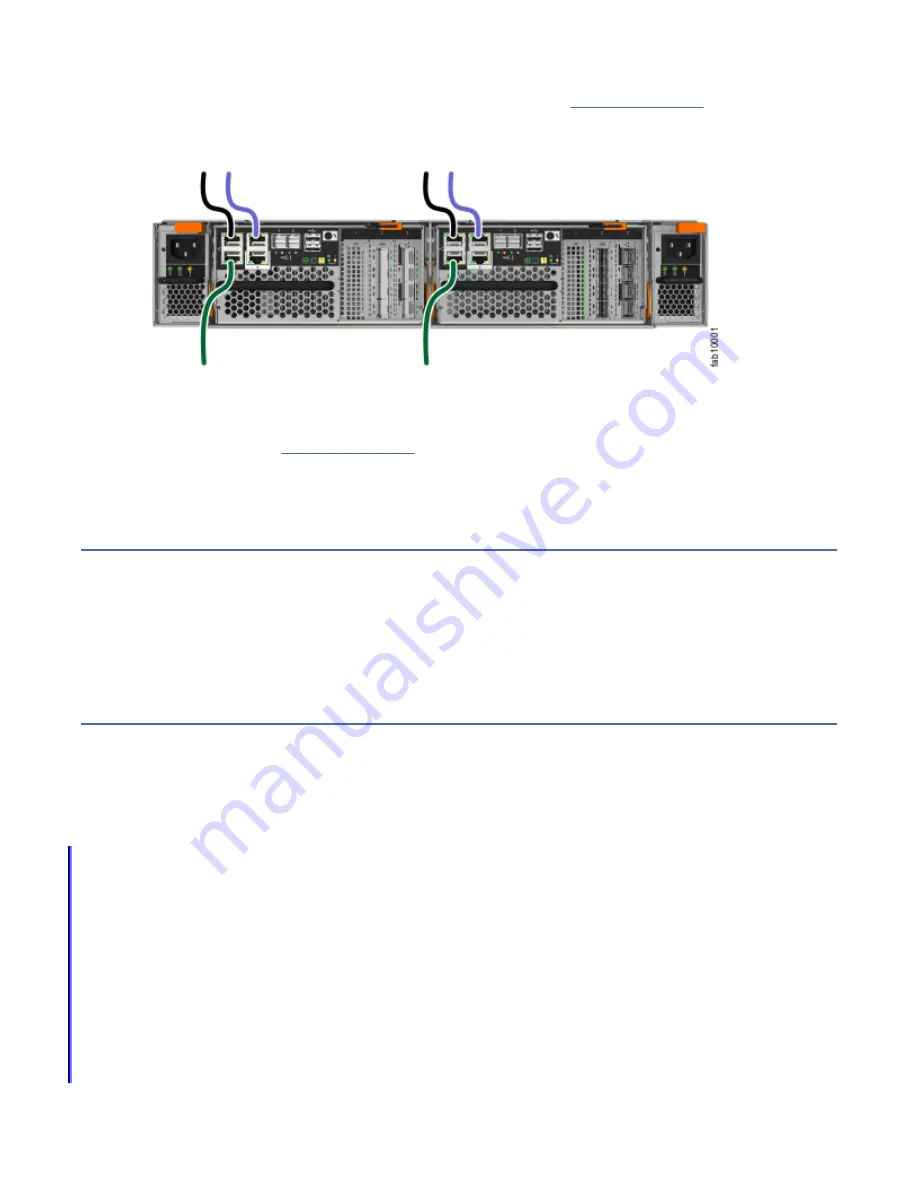
1. Connect Ethernet port 1 of each node canister in the system to the IP network that will provide
connection to the system management interfaces, as shown in Figure 6 on page 18.
This port can also be used for iSCSI connectivity to the system by hosts on the network. Where more
than one control enclosure is present in the system, ensure port 1 of every node canister is connected
to the same network to provide access if the configuration node fails.
Figure 6. Connecting the Ethernet cables
2. Optionally, connect Ethernet port 2 of each node canister in the system to a second IP network that
will provide redundant connection to the system management interfaces, as shown by the lighter
cable connection in Figure 6 on page 18.
This port can also be used for iSCSI connectivity to the system by hosts on the network. If there is
more than one control enclosure in the system, ensure that port 2 of every node canister is connected
to the same network to provide access if the configuration node fails.
If your system has one or more 4-port 16 Gbps Fibre Channel adapters installed, use Fibre Channel
cables to connect the two node canisters in the enclosure to the switches in the Fibre Channel SAN.
Procedure
To install the cables, complete the following steps.
Initializing the system with the technician port
To initialize the system, you connect a computer to a technician port of the node canister by using an
Ethernet cable, and then open a wizard in a supported web browser.
Before you begin
Important:
• Browser security features might prompt the user before it accepts the self-signed certificate that the
system issues.
• It might be necessary to remove old certificates that are stored in the browser before the browser
accepts the request.
• The web browser might display a warning about a potential security risk. It is safe to accept the risk and
continue.
• After the technician port physical connection is completed (that is, connected both ends), it can take up
to 45 seconds before the port is fully up and able to process requests. Submitting requests before this
interval might result in 404 error responses.
• If the
http://service
request in the browser causes a 404 error, or fails to produce a response, it
might be necessary to use the url
https://192.168.0.1
in the browser request to connect to the
system.
18 SAN Volume Controller 8.3.1: Machine Types 2145, 2147 Models SA2, SV2
Summary of Contents for SAN Volume Controller 2145
Page 1: ...SAN Volume Controller 8 3 1 Quick Start Guide Machine Types 2145 2147 Models SA2 SV2 IBM...
Page 4: ...iv...
Page 6: ...vi SAN Volume Controller 8 3 1 Machine Types 2145 2147 Models SA2 SV2...
Page 32: ...12 SAN Volume Controller 8 3 1 Machine Types 2145 2147 Models SA2 SV2...
Page 42: ...22 SAN Volume Controller 8 3 1 Machine Types 2145 2147 Models SA2 SV2...
Page 44: ...24 SAN Volume Controller 8 3 1 Machine Types 2145 2147 Models SA2 SV2...
Page 45: ......


