


Soft-
ware
93F2367
59G9531
59G9531
59G9531
59G9531
93F2367
93F2367
59G9531
59G9531
59G9531
93F2367
93F2367
93F2367
93F2367
93F2367
Modem
93F0024
34G1854
34G1854
93F0024
93F0024
93F0024
93F0024
34G1854
34G1854
34G1854
93F0024
93F0024
93F0024
93F0024
93F0024
Display
33G5373
59G7874
59G7874
33G4393
68G2622
33G5373
33G5373
59G7874
59G7874
59G7874
33G4393
33G4393
33G5373
33G4393
33G5373
Power
Supply
93F2392
52G8741
60G1996
93F2390
93F2390
93F2392
93F2392
52G8741
52G8741
60G1996
93F2390
93F2390
93F2392
93F2390
93F2392
Hard
Drive
93F0118
59G9562
59G9562
59G9567
93F2363
93F0118
93F2363
59G9562
59G9564
59G9564
59G9567
93F2329
93F2363
93F2329
93F2363
Drive B
(5.25-in)
93F2362
93F2362
93F2362
N/A
93F2362
93F2362
93F2362
93F2362
93F2362
93F2362
N/A
93F2362
93F2362
N/A
93F2362
Disk Drives
Drive A
(3.5-in)
93F2361
93F2361
93F2361
93F2361
93F2361
93F2361
93F2361
93F2361
93F2361
93F2361
93F2361
93F2361
93F2361
93F2361
93F2361
Memory
N/A
92F0105
64F3686
92F0102
92F0105
N/A
N/A
92F0105
92F0105
64F3686
N/A
N/A
N/A
N/A
N/A
Basic
Board
N/A
N/A
N/A
N/A
N/A
N/A
N/A
N/A
N/A
N/A
N/A
N/A
N/A
N/A
N/A
System Board
Filled
Board
34G1894
34G1942
34G1881
34G1871
34G1872
34G1848
34G1893
34G1876
34G1942
34G1881
93F2397
93F2397
93F2398
34G1885
34G1885
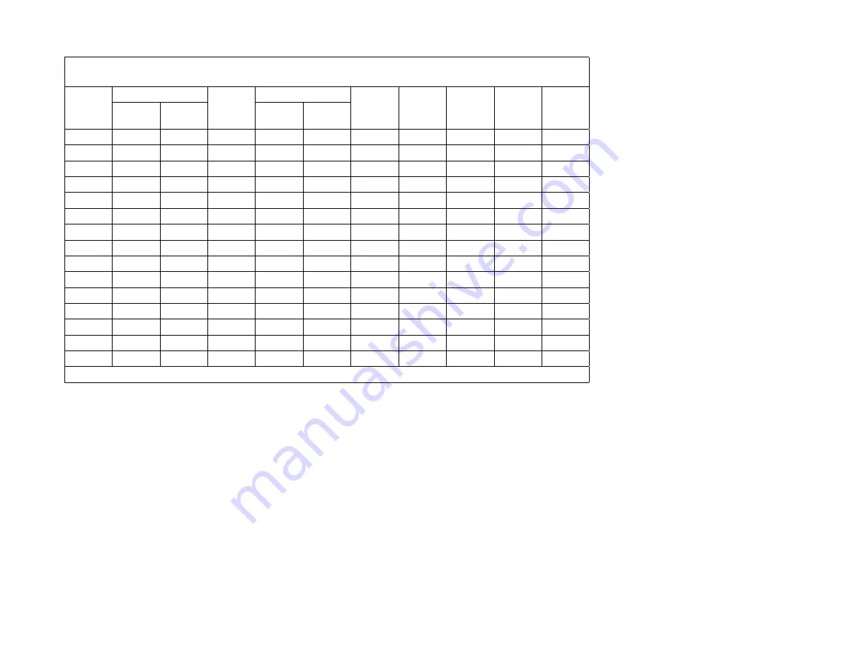
Table
A-1 (Page 2 of 4). U.S. Machine Types 2133/2155/2168 (Factory-Installed Parts). Refer to “System Board
Layouts” on page 5-2 for system board details and to “Parts Catalog” on page 7-1 for parts assemblies.
Model
G78
G82
G87
M40
M46
P57
P71
P74
P84
P89
S11
S13
S14
S43
S44
N/A = FRU part number varies. See “Parts Catalog” on page 7-1.
Appendix.
Model
Configurations
and
FRU
Part
Numbers
A-3
Summary of Contents for PS/1
Page 1: ...M achine Types 2133 2155 and 2168...
Page 2: ......
Page 3: ...M achine Types 2133 2155 and 2168...
Page 8: ...Index X 1 vi...
Page 14: ...xii...
Page 38: ...1 24...
Page 40: ...Notes 2 2...
Page 67: ...Notes Diagnostic Information 2 29...
Page 95: ...Notes Diagnostic Information 2 57...
Page 112: ...MAP 1100 continued 003 continued Replace the system board 2 74...
Page 116: ...MAP 1200 continued 009 Replace the serial port adapter card 2 78...
Page 134: ...Notes 2 96...
Page 170: ...3 12...
Page 175: ...1005 Cover Cover release Latch Repair Information 4 5...
Page 185: ...1045 Riser Card Adapter Card 1035 Left DASD Support Bracket 1010 Repair Information 4 15...
Page 200: ...Figure 4 20 Pull Out on the Cover 4 30...
Page 250: ...5 32...
Page 252: ...6 2...
Page 255: ...Catalog Section Parts Catalog 7 3...
Page 256: ...Assembly 1 Machine Types 2133 and 2155 System Unit Exterior 3 1 2 7 4...
Page 258: ...Assembly 2 Machine Types 2133 and 2155 System Unit Interior 1 2 3 4 5 6 7 8 11 12 12 10 7 6...
Page 261: ...12 93F0041 1 Packet Mounting Screws Parts Catalog 7 9...
Page 262: ...Assembly 3 Machine Type 2168 System Unit Exterior 2 1 7 10...
Page 267: ...Parts Catalog 7 15...
Page 268: ...Assembly 5 Diskette and Hard Disk Drives All Machine Types 1 2 3 4 4 4 4 4 7 16...
Page 273: ...Parts Catalog 7 21...
Page 274: ...Assembly 7 Keyboard and Mouse All Machine Types 1 2 7 22...
Page 284: ...Part Asm Number Index Page 93F2397 2 1 7 7 93F2398 2 1 7 7 93F2399 2 1 7 7 8 4...
Page 290: ...This page left blank intentionally A 6...
Page 296: ...This page left blank intentionally A 12...
Page 298: ...This page left blank intentionally A 14...
Page 304: ...IBM Part Number 63G2028 IBM United Kingdom PO Box 41 North Harbour Portsmouth PO6 3AU England...


