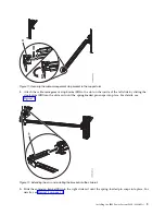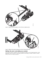
6.
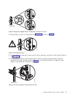
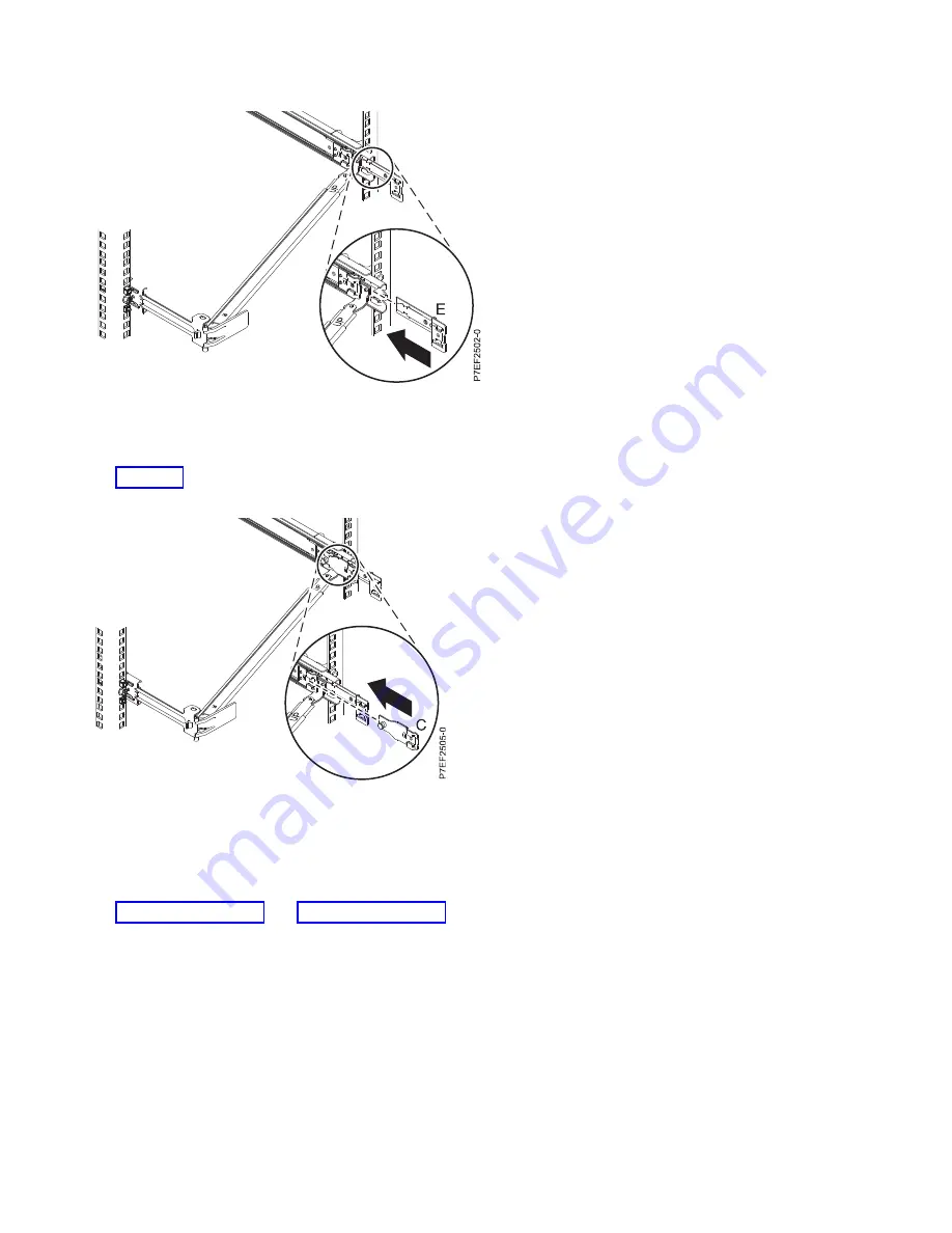
Attach the cable-management stop bracket (B) to the slot on the inside of the left slide by sliding the
stop bracket (B) into the slide rail until the spring-loaded pin snaps into place. For details, see
Figure 14.
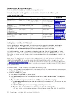
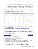
7.
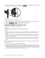
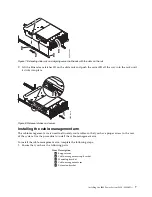
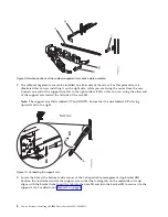
Place the cable-management arm (D) on the support arm (A). Slide the first cable-management arm
tab into the slot on the mounting bracket (C). Push the tab until the spring-loaded latch snaps into
place. Slide the other cable-management arm tab into the extension bracket (E) on the outside of the
right slide rail (2). Push the tab until the spring-loaded latch snaps into place. For details, see
Figure 15 on page 11 and Figure 16 on page 11.
Figure 13. Installing the extension bracket into the slide rail
Figure 14. Installing the mounting bracket into the slide rail
10
Power Systems: Installing the IBM Power System S824 (8286-42A)
Summary of Contents for Power System S824
Page 1: ...Power Systems Installing the IBM Power System S824 8286 42A GI11 9905 06 IBM...
Page 2: ......
Page 3: ...Power Systems Installing the IBM Power System S824 8286 42A GI11 9905 06 IBM...
Page 6: ...iv Power Systems Installing the IBM Power System S824 8286 42A...
Page 16: ...xiv Power Systems Installing the IBM Power System S824 8286 42A...
Page 50: ...34 Power Systems Installing the IBM Power System S824 8286 42A...
Page 62: ...46 Power Systems Installing the IBM Power System S824 8286 42A...
Page 63: ......
Page 64: ...IBM Part Number 01LK523 Printed in USA GI11 9905 06 1P P N 01LK523...

