4.
Note:
Removing or replacing this feature is a customer task. You can complete this task yourself, or
contact a service provider to complete the task for you. You might be charged a fee by the service
provider for this service.
Preparing the 8284-21A or 8284-22A system to remove and replace a disk drive or
solid-state drive by using the hot-spare function with the power turned on in IBM i
Learn about the steps you must complete before you remove and replace a disk drive or solid-state drive
(SSD) by using the hot-spare function in a system with the IBM i operating system or IBM i logical
partition that controls the drive location powered on.
To prepare the system to remove and replace a disk drive or solid-state drive, complete the following
steps:
1.
Determine the protection status of the disk drive or solid-state drive that you are replacing. For
instructions, see “Determining the disk drive or solid-state drive protection status in the IBM i
operating system” on page 118.
2.
If you are removing a solid-state device that is on a PCIe RAID and SSD SAS adapter, go to
Replacing an SSD module on the PCIe RAID and SSD SAS adapter and complete that procedure.
3.
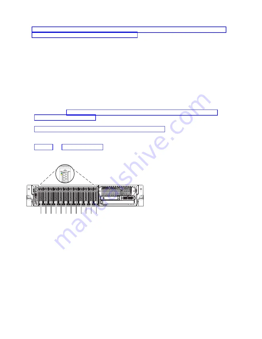
Identify the part and the system that you want to service. The disk drive and SSD slots are in the
front of a system. More SSD slots are also available in an expanded function system.
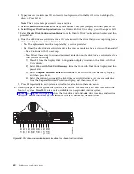
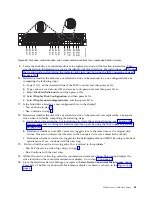
Figure 70 and Figure 71 on page 73 show the disk drive and solid-state drive locations and service
indicators. Service indicators are located above the latch handle on the disk drives.
P2-D12
P2-D1
1
P2-D10
P2-D9
P2-D8
P2-D7
P2-D6
P2-D5
P2-D4
P2-D3
P2-D2
P2-D1
P8HAL508-0
Figure 70. Disk drive and service indicator locations for a base function system
72
Disk drives or solid-state drives
Summary of Contents for Power System 5148-21L
Page 2: ......
Page 18: ...xvi Disk drives or solid state drives ...
Page 202: ...184 Disk drives or solid state drives ...
Page 203: ......
Page 204: ...IBM ...


