background image

4.

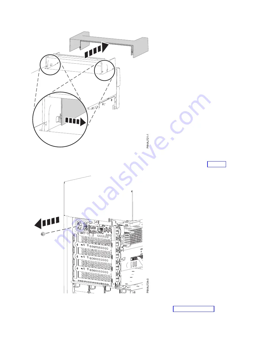
Remove the rear screw from the side cover by using a Phillips screwdriver as shown in Figure 25.

5.

Slide the side cover off of the system in the direction that is shown in Figure 26 on page 42.

Figure 24. Removing the handle cover from an 8286-41A stand-alone system

Figure 25. Removing the screw from the 8286-41A side cover

Common procedures for removing or replacing the PCIe3 x8 SAS RAID internal adapter 6 Gb

41

Summary of Contents for PCIe3 x8 SAS RAID internal adapter 6 Gb

Page 1: ...Power Systems PCIe3 x8 SAS RAID internal adapter 6 Gb for the 5148 21L 5148 22L 8247 21L 8247 22L 8284 21A or 8284 22A IBM ...

Page 2: ......

Page 3: ...Power Systems PCIe3 x8 SAS RAID internal adapter 6 Gb for the 5148 21L 5148 22L 8247 21L 8247 22L 8284 21A or 8284 22A IBM ...

Page 4: ...y Notices manual G229 9054 and the IBM Environmental Notices and User Guide Z125 5823 This edition applies to IBM Power Systems servers that contain the POWER8 processor and to all associated models Copyright IBM Corporation 2014 2017 US Government Users Restricted Rights Use duplication or disclosure restricted by GSA ADP Schedule Contract with IBM Corp ...

Page 5: ...ode and LED support status 24 Identifying a part by using the operating system or VIOS 25 Identifying a part in an AIX system or logical partition 25 Finding the location code for a part in an AIX system or logical partition 25 Activating the indicator light for a part by using AIX diagnostics 25 Identifying a part in an IBM i system or logical partition 26 Finding the location code and activating...

Page 6: ...41A or 8286 42A system 50 Installing the service access cover on a rack mounted 5148 21L 5148 22L 8247 21L 8247 22L 8247 42L 8284 21A 8284 22A 8286 41A or 8286 42A system 50 Installing the service access cover on a stand alone 8286 41A system 51 Air baffle 52 Opening the air baffle on an 8247 42L 8286 41A or 8286 42A system 52 Closing the air baffle on an 8247 42L 8286 41A or 8286 42A system 53 Re...

Page 7: ...ing a system attention LED by using the operating system or VIOS tools 95 Deactivating the indicator light for a part by using AIX diagnostics 95 Deactivating the indicator light by using the IBM i operating system 95 Deactivating the indicator light by using the Linux operating system 96 Deactivating the indicator light for a part by using the VIOS tools 96 Deactivating a system attention LED by ...

Page 8: ...vi PCIe3 x8 SAS RAID internal adapter 6 Gb ...

Page 9: ...tional copies of safety information documentation can be obtained by calling the IBM Hotline at 1 800 300 8751 German safety information Das Produkt ist nicht für den Einsatz an Bildschirmarbeitsplätzen im Sinne 2 der Bildschirmarbeitsverordnung geeignet Laser safety information IBM servers can use I O cards or features that are fiber optic based and that utilize lasers or LEDs Laser compliance IB...

Page 10: ... To Disconnect 1 Turn off everything unless instructed otherwise 2 For AC power remove the power cords from the outlets 3 For racks with a DC power distribution panel PDP turn off the circuit breakers located in the PDP and remove the power from the Customer s DC power source 4 Remove the signal cables from the connectors 5 Remove all cables from the devices To Connect 1 Turn off everything unless...

Page 11: ...emperatures will exceed the manufacturer s recommended ambient temperature for all your rack mounted devices v Do not install a unit in a rack where the air flow is compromised Ensure that air flow is not blocked or reduced on any side front or back of a unit used for air flow through the unit v Consideration should be given to the connection of the equipment to the supply circuit so that overload...

Page 12: ... to eliminate potential hazards v Verify that the route that you choose can support the weight of the loaded rack cabinet Refer to the documentation that comes with your rack cabinet for the weight of a loaded rack cabinet v Verify that all door openings are at least 760 x 230 mm 30 x 80 in v Ensure that all devices shelves drawers doors and cables are secure v Ensure that the four leveling pads a...

Page 13: ...DANGER Rack mounted devices are not to be used as shelves or work spaces L002 L003 1 2 or 1 2 or 1 2 3 4 or Safety notices xi ...

Page 14: ...uct might be equipped with multiple AC power cords or multiple DC power cables To remove all hazardous voltages disconnect all power cords and power cables L003 L007 CAUTION A hot surface nearby L007 L008 xii PCIe3 x8 SAS RAID internal adapter 6 Gb ...

Page 15: ...tacle Although shining light into one end and looking into the other end of a disconnected optical fiber to verify the continuity of optic fibers many not injure the eye this procedure is potentially dangerous Therefore verifying the continuity of optical fibers by shining light into one end and looking at the other end is not recommended To verify continuity of a fiber optic cable use an optical ...

Page 16: ...d under overhanging load v Do not use on uneven surface incline or decline major ramps v Do not stack loads v Do not operate while under the influence of drugs or alcohol v Do not support ladder against LIFT TOOL v Tipping hazard Do not push or lean against load with raised platform v Do not use as a personnel lifting platform or step No riders v Do not stand on any part of lift Not a step v Do no...

Page 17: ...lding interfaces only Type 2 or Type 4 ports as described in GR 1089 CORE and require isolation from the exposed OSP cabling The addition of primary protectors is not sufficient protection to connect these interfaces metallically to OSP wiring Note All Ethernet cables must be shielded and grounded at both ends The ac powered system does not require the use of an external surge protection device SP...

Page 18: ...xvi PCIe3 x8 SAS RAID internal adapter 6 Gb ...

Page 19: ...nternal adapter 6 Gb Learn how to prepare the system to install a PCIe3 x8 SAS RAID internal adapter 6 Gb To prepare the system to install a SAS RAID internal adapter complete the following steps 1 Ensure that the software that is required to support the feature is installed on your system For information about software prerequisites see the IBM Prerequisite website http www 912 ibm com e_dir eSer...

Page 20: ...r 8284 22A Learn how to install the PCIe3 x8 SAS RAID internal adapter 6 Gb To complete this procedure you must have prepared the system to install the PCIe3 x8 SAS RAID internal adapter 6 Gb For instructions see Preparing the system to install a PCIe3 x8 SAS RAID internal adapter 6 Gb on page 1 To install the PCIe3 x8 SAS RAID internal adapter 6 Gb FC EJ0V or FC EL3V complete the following steps ...

Page 21: ...tic guide block on the side of the system chassis as shown in Figure 2 A P8EG5501 1 Figure 1 Disconnecting the front SAS cables from the disk drive backplane Figure 2 Removing the front SAS cables from the guide block PCIe3 x8 SAS RAID internal adapter 6 Gb 3 ...

Page 22: ...rnal adapter in slot P1 C14 Route the front SAS cable into position while you are lowering the PCIe3 x8 SAS RAID internal adapter 6 Gb into the slot 10 Complete the installation of the PCIe3 x8 SAS RAID internal adapter 6 Gb by fully seating it Ensure that the adapter is installed on locating pin A Press the top center edge of the card down to firmly seat it into the system backplane connector as ...

Page 23: ...g the SAS RAID adapter into the slot 17 Complete the installation of the SAS RAID adapter by fully seating it Ensure that the adapter is installed on locating pin A Press the top center edge of the card down to firmly seat it into the system backplane connector See Figure 5 on page 6 18 Push the blue handles B in the direction that is shown See Figure 5 on page 6 19 Push the cable retention bracke...

Page 24: ...S cables into the plastic guide block on the side of the chassis Figure 5 Installing the PCIe3 x8 SAS RAID internal adapter 6 Gb in slot P1 C15 Figure 6 Routing the front SAS cables 6 PCIe3 x8 SAS RAID internal adapter 6 Gb ...

Page 25: ...21L 8247 22L 8284 21A or 8284 22A system parts http www ibm com support knowledgecenter POWER8 p8ecs p8ecs_83x_8rx_parts htm 22 Replace the fan cage with the fans installed For instructions see Replacing a fan cage http www ibm com support knowledgecenter POWER8 p8haq p8haq_83x_8rx_fancagereplace htm P8EG5506 0 Figure 7 Reconnecting the front SAS cables in the disk drive backplane J2 J1 Storage Co...

Page 26: ...alled part For instructions see Verifying the installed part on page 66 Removing and replacing the PCIe3 x8 SAS RAID internal adapter 6 Gb in the 5148 21L 5148 22L 8247 21L 8247 22L 8284 21A or 8284 22A Learn how to remove and replace a PCIe3 x8 SAS RAID internal adapter 6 Gb If your system is managed by the Hardware Management Console HMC use the HMC to repair a part in the system For instruction...

Page 27: ...e v When you use an ESD wrist strap follow all electrical safety procedures An ESD wrist strap is used for static control It does not increase or decrease your risk of receiving electric shock when using or working on electrical equipment v If you do not have an ESD wrist strap just prior to removing the product from ESD packaging and installing or replacing hardware touch an unpainted metal surfa...

Page 28: ...ce from the system by unplugging the system For instructions see Disconnecting the power cords from the system on page 58 Note The system might be equipped with redundant power supply Before you continue with this procedure ensure that all power to your system is disconnected L003 1 2 or P8ECS505 1 A B C D E F G H I J Figure 9 Service indicator LEDs 10 PCIe3 x8 SAS RAID internal adapter 6 Gb ...

Page 29: ...ER Multiple power cords The product might be equipped with multiple AC power cords or multiple DC power cables To remove all hazardous voltages disconnect all power cords and power cables L003 PCIe3 x8 SAS RAID internal adapter 6 Gb 11 ...

Page 30: ... on and that the ESD clip is connected to an unpainted metal surface If not do so now 2 Remove the fan cage For instructions see Removing a fan cage http www ibm com support knowledgecenter POWER8 p8haq p8haq_83x_8rx_fancageremove htm 3 Label the front SAS cables that are attached to the SAS RAID internal adapter that you want to remove Press the latch A and unplug the connector of the cable from ...

Page 31: ...he blue handles B in the direction that is shown in Figure 12 on page 14 7 Lift the SAS RAID internal adapter out of the slot with the front SAS cables still connected to the adapter Ensure that the front SAS cables do not get caught on any components while you are lifting the SAS RAID internal adapter out of the slot Figure 11 Removing the front SAS cable from the guide block PCIe3 x8 SAS RAID in...

Page 32: ...arge ESD wrist strap on and that the ESD clip is connected to an unpainted metal surface If not do so now 2 Reconnect the front SAS cables to the PCIe3 x8 SAS RAID internal adapter 6 Gb front connector P1 or P2 before you install the adapter as shown in Figure 13 on page 15 Push the cable connector in until the connector latch clicks 3 Route the front SAS cables into position while you are lowerin...

Page 33: ...ide block on the side of the chassis as shown in Figure 14 P8EGM501 0 A B C Figure 13 Replacing the PCIe3 x8 SAS RAID internal adapter 6 Gb Figure 14 Routing the front SAS cables into the guide block PCIe3 x8 SAS RAID internal adapter 6 Gb 15 ...

Page 34: ... adapter See Figure 16 v If you have two PCIe3 x8 SAS RAID internal adapters CCIN 57D7 split disk feature the short SAS cable connects the upper disk drive backplane connector J2 to the P2 connector on the adapter in slot P1 C14 The long SAS cable connects the lower disk drive backplane connector J1 to the P1 connector on the adapter in slot P1 C15 See Figure 17 on page 17 P8EG5506 0 Figure 15 Rec...

Page 35: ...ver on a 5148 21L 5148 22L 8247 21L 8247 22L 8247 42L 8284 21A 8284 22A 8286 41A or 8286 42A system on page 50 3 Remove the electrostatic discharge ESD wrist strap 4 For a rack mounted system place the system into the operating position For instructions see Placing the rack mounted system into the operating position on page 58 5 Reconnect the power cords to the system For instructions see Connecti...

Page 36: ...18 PCIe3 x8 SAS RAID internal adapter 6 Gb ...

Page 37: ...power to the product ensure all power cables are properly connected For racks with AC power connect all power cords to a properly wired and grounded electrical outlet Ensure that the outlet supplies proper voltage and phase rotation according to the system rating plate For racks with a DC power distribution panel PDP connect the customer s DC power source to the PDP Ensure that the proper polarity...

Page 38: ...nstall servers and optional devices starting from the bottom of the rack cabinet v Rack mounted devices are not to be used as shelves or work spaces Do not place objects on top of rack mounted devices In addition do not lean on rack mounted devices and do not use them to stabilize your body position for example when working from a ladder v Each rack cabinet might have more than one power cord For ...

Page 39: ... you have a current backup of your system or logical partition including operating systems licensed programs and data 3 Review the installation or replacement procedure for the feature or part 4 Note the significance of color on your system Blue or terra cotta on a part of the hardware indicates a touch point where you can grip the hardware to remove it from or install it in the system open or clo...

Page 40: ...or system information indicator by using the ASMI on page 97 Identifying the enclosure or server that contains the part Learn how to determine which server or enclosure has the part you want to replace Enabling enclosure or server indicators with the ASMI Find out how to enable enclosure or server indicators by using the Advanced System Management Interface ASMI To perform this operation you must ...

Page 41: ...heck log light No light indicates that the system is operating normally Light on indicates that the system requires attention v D Enclosure fault light A constant light indicates a fault in the system unit No light indicates that the system is operating normally v E Eject button v F Function Data display v G Pinhole reset button v H Decrement button v I Enter button v J Increment button Activating...

Page 42: ...vate LED The associated LED is turned on Finding the part location code and LED support status You can use location codes for the server you are working with to find the part location code and whether there is Identify LED support To find the location code and to determine if there is identify LED support complete the following steps 1 Select the server you are working on to see the location codes...

Page 43: ...on Use these instructions to learn how to locate a part activate the indicator light for the part and deactivate the indicator light for the part on a system or logical partition running the AIX operating system Finding the location code for a part in an AIX system or logical partition You might need to use AIX tools before activating the indicator light to locate a part To configure the AIX syste...

Page 44: ...ess Enter Remember The service tools password is case sensitive 4 Select Start a service tool from the System Service Tools SST display and press Enter 5 Select Hardware service manager from the Start a Service Tool display and press Enter 6 Select Work with service action log from the Hardware Service Manager display and press Enter 7 On the Select Timeframe display change the From Date and Time ...

Page 45: ...on_code and press Enter 3 Look for the system attention light to identify the enclosure that contains the part Important A flashing amber LED indicates the location of the part and a solid amber LED indicates that the part is failing Related information Service and productivity tools for Linux on Power servers IBM provides hardware diagnostic aids and productivity tools and installation aids for L...

Page 46: ... For more information see Accessing the Advanced System Management Interface by using a web browser http www ibm com support knowledgecenter POWER8 p8ect pxect_browser htm For IBM Power Systems that contain the POWER8 processor the identify LEDs can be used to identify or verify the location of a part that you intend to install remove or replace The identify function flashing the amber LED corresp...

Page 47: ...play 3 Select the server or enclosure with the part that needs to be replaced and click Continue The location code identifiers are listed 4 Select the location code identifier and select Identify 5 To save the changes made to the state of one or more FRU indicators click Save settings Identifying a part by using the HMC You can use the following procedures to activate light emitting diodes LEDs by...

Page 48: ...cal partition after performing a service action or system upgrade Starting a system that is not managed by an HMC You can use the power button or the Advanced System Management Interface ASMI to start a system that is not managed by a Hardware Management Console HMC Starting a system by using the control panel You can use the power button on the control panel to start a system that is not managed ...

Page 49: ...that the system is operating normally Light on indicates that the system requires attention v D Enclosure fault roll up light A constant light indicates a fault in the enclosure No light indicates that the system is operating normally v E Eject button v F Function Data display v G Pinhole reset button v H Decrement button v I Enter button v J Increment button 4 Observe the following aspects after ...

Page 50: ...l partition by using the HMC Classic or HMC Enhanced interface To start the system by using the HMC Classic or HMC Enhanced interface complete the following steps 1 Verify that the logical partition start policy is set to User Initiated by completing the following steps a In the navigation area expand Systems Management Servers b In the content pane select the managed system c In the Tasks area cl...

Page 51: ...r Initiated Starting an IBM PowerKVM system You can use the Intelligent Platform Management Interface IPMI to start an IBM PowerKVM system To start an IBM PowerKVM system run the ipmitool I lanplus H FSP IP P ipmipassword chassis power on command from a remote system Stopping a system or logical partition Learn how to stop a system or logical partition as a part of a system upgrade or service acti...

Page 52: ...are connected to the system to off Stopping a system by using the ASMI You might need to stop the system to complete another task If your system is not managed by the Hardware Management Console HMC use these instructions to stop the system by using the Advanced System Management Interface ASMI To stop a system by using the ASMI complete the following steps 1 On the ASMI Welcome pane specify your ...

Page 53: ...logical partition by using the HMC Enhanced Tech Preview Pre GA or HMC Enhanced interface complete the following steps 1 You must deactivate all the active logical partitions before powering off the system To deactivate logical partitions for a specific system complete the following steps a In the navigation area click the Resources icon and then click All Systems b Click the system name for which...

Page 54: ...ice Removing the front cover Use these instructions to remove the front cover from a 5148 21L 5148 22L 8247 21L 8247 22L 8247 42L 8284 21A 8284 22A 8286 41A or 8286 42A system so that you can access the hardware parts or perform service Removing the front cover from a rack mounted 5148 21L 5148 22L 8247 21L 8247 22L 8284 21A or 8284 22A system Use this procedure to remove the cover from a rack mou...

Page 55: ...discharge ESD wrist strap attached If not attach it now 2 Remove the two shipping screws A if present that secure the system to the rack Note Replacing the shipping screws is optional but should be done in geographic areas that are prone to seismic activity 3 Pull the cover away from the system The cover has an indentation where you can hold onto it more easily A P8HAJ550 0 Figure 20 Removing the ...

Page 56: ...lete the following steps 1 Open the front door 2 Ensure that you have the electrostatic discharge ESD wrist strap attached If not attach it now 3 Pull the blue tab A to open the bezel door 4 Push the blue latch B located above the USB ports in the direction shown on the latch and then pull the front cover away from the system A P8HAJ650 0 Figure 21 Removing the front cover 38 PCIe3 x8 SAS RAID int...

Page 57: ...king station so that you can access components or perform service To remove the side cover complete the following steps 1 Remove the plastic piece within the interior of the handle cover by pushing the latches on the inside firmly and sliding it out See Figure 23 on page 40 Figure 22 Removing the front cover Common procedures for removing or replacing the PCIe3 x8 SAS RAID internal adapter 6 Gb 39...

Page 58: ...r to disengage the side latches 3 Remove the handle cover by sliding it toward the front of the system then lifting upwards See Figure 24 on page 41 Figure 23 Removing the piece within the handle cover on an 8286 41A stand alone system 40 PCIe3 x8 SAS RAID internal adapter 6 Gb ...

Page 59: ...the side cover off of the system in the direction that is shown in Figure 26 on page 42 Figure 24 Removing the handle cover from an 8286 41A stand alone system Figure 25 Removing the screw from the 8286 41A side cover Common procedures for removing or replacing the PCIe3 x8 SAS RAID internal adapter 6 Gb 41 ...

Page 60: ... 22L 8284 21A or 8284 22A system To install the front cover complete the following steps 1 Ensure that you have the electrostatic discharge ESD wrist strap attached If not attach it now 2 Slide the cover onto the system 3 Close the release latches by pushing in the direction shown in Figure 27 on page 43 The cover snaps into place and has an indentation where you can hold onto it more easily 4 Rep...

Page 61: ...sh the cover onto the system 3 Gently push the cover in until the cover clips A are seated in their respective mounting posts as shown in the following figure The cover snaps into place and has an indentation where you can hold onto it more easily 4 Replace the shipping screws B Note Replacing the shipping screws is optional but should be done in geographic areas that are prone to seismic activity...

Page 62: ...orm service To install the front cover and front door complete the following steps 1 Ensure that you have the electrostatic discharge ESD wrist strap attached If not attach it now 2 Align the cover until the two cover tabs A are seated into the slots on the base plate B as shown in the following figure B A P8HAJ651 1 Figure 28 Installing the front cover 44 PCIe3 x8 SAS RAID internal adapter 6 Gb ...

Page 63: ...aaaaaaaaaaaaa aaaaaaaaaaaaaaaaaaaaaaaaaaaaaaaaaaaaaaaaaaaaaaaaaaaaaaaaaaaaaaaa aaaaaaaaaaaaaaaaaaaaaaaaaaaaaaaaaaaaaaaaaaaaaaaaaaaaaaaaaaaaaaaa aaaaaaaaaaaaaaaaaaaaaaaaaaaaaaaaaaaaaaaaaaaaaaaaaaaaaaaaaaaaaaaa aaaaaaaaaaaaaaaaaaaaaaaaaaaaaaaaaaaaaaaaaaaaaaaaaaaaaaaaaaaaaaaa aaaaaaaaaaaaaaaaaaaaaaaaaaaaaaaaaaaaaaaaaaaaaaaaaaaaaaaaaaaaaaaa aaaaaaaaaaaaaaaaaaaaaaaaaaaaaaaaaaaaaaaaaaaaaaaaaaaaaaaaaaaaa...

Page 64: ...n in Figure 32 3 Place the side cover down over the 8286 41A system 4 Slide the side cover into place until secured onto the system as shown in the following figure Note Ensure that the side cover tabs are aligned properly Figure 31 Securing the handle cover in an 8286 41A stand alone system Figure 32 Inserting the piece within the handle cover on an 8286 41A stand alone system 46 PCIe3 x8 SAS RAI...

Page 65: ...ide cover rear screw with a Phillips screwdriver as shown in Figure 34 on page 48 Figure 33 Installing the 8286 41A side cover Common procedures for removing or replacing the PCIe3 x8 SAS RAID internal adapter 6 Gb 47 ...

Page 66: ...on Operating the system without the cover for more than 30 minutes might damage the system components To remove the service access cover from a rack mounted system complete the following steps 1 Ensure that you have the electrostatic discharge ESD wrist strap attached If not attach it now 2 Release the latch by pushing the release latch A in the direction shown 3 Slide the cover B off the system u...

Page 67: ...stem complete the following steps 1 Ensure that you have the electrostatic discharge ESD wrist strap attached If not attach it now 2 Release the latch by pushing the release latch A in the direction shown 3 Slide the cover B off the system unit When the front of the service access cover has cleared the upper frame ledge lift the cover up and off the system unit Attention For proper cooling and air...

Page 68: ...his procedure to install the service access cover on a rack mounted 5148 21L 5148 22L 8247 21L 8247 22L 8247 42L 8284 21A 8284 22A 8286 41A or 8286 42A system To install the service access cover on a rack mounted system complete the following steps 1 Ensure that you have the electrostatic discharge ESD wrist strap attached If not attach it now 2 Slide the cover B on to the system unit 3 Close the ...

Page 69: ... on a stand alone system complete the following steps 1 Ensure that you have the electrostatic discharge ESD wrist strap attached If not attach it now 2 Slide the cover B on to the system unit 3 Close the latch release A by pushing it in the direction shown Figure 37 Installing the service access cover Common procedures for removing or replacing the PCIe3 x8 SAS RAID internal adapter 6 Gb 51 ...

Page 70: ...to open the air baffle on an 8247 42L 8286 41A or 8286 42A system To open the air baffle complete the following steps 1 Ensure that you have the electrostatic discharge ESD wrist strap attached If not attach it now 2 Pull the latches A to disengage the air baffle from the chassis 3 Lift the air baffle B up to open it Figure 38 Installing the service access cover 52 PCIe3 x8 SAS RAID internal adapt...

Page 71: ...complete the following steps 1 Ensure that you have the electrostatic discharge ESD wrist strap attached If not attach it now 2 Push down the air baffle B toward the chassis 3 Press the side latches A to latch the air baffle to the chassis P8HAJ607 1 A B Figure 39 Opening the air baffle Common procedures for removing or replacing the PCIe3 x8 SAS RAID internal adapter 6 Gb 53 ...

Page 72: ...8286 42A system To remove the air baffle complete the following steps 1 Ensure that you have the electrostatic discharge ESD wrist strap attached If not attach it now 2 Pull the air baffle to disengage it from the chassis clasp A 3 Lift the air baffle up to remove it Figure 40 Closing the air baffle 54 PCIe3 x8 SAS RAID internal adapter 6 Gb ...

Page 73: ...e following steps 1 Ensure that you have the electrostatic discharge ESD wrist strap attached If not attach it now 2 Push the air baffle toward the chassis 3 Fix the air baffle to the chassis by pushing the clasp onto the chassis A until it locks into place P8HAJ615 0 A Figure 41 Removing the air baffle Common procedures for removing or replacing the PCIe3 x8 SAS RAID internal adapter 6 Gb 55 ...

Page 74: ...hat only one system unit is in the service position at a time v Ensure that the cables at the rear of the system unit do not catch or bind as you pull the system unit forward in the rack v When the rails are fully extended the rail safety latches lock into place This action prevents the system from being pulled out too far To place a rack mounted system into the service position complete the follo...

Page 75: ...s to slide out the Central Electronics Complex CEC assembly A P8HAJ652 0 Figure 43 Removing the front screws P8HAJ603 1 B Figure 44 Releasing the side latches Common procedures for removing or replacing the PCIe3 x8 SAS RAID internal adapter 6 Gb 57 ...

Page 76: ...until both system unit release latches lock into position 4 Secure the server to the rack by using shipping screws 5 If you have not already done so replace the front cover For instructions see Installing the front cover on page 42 Power cords Use these procedures to disconnect and connect the power cords on IBM Power Systems servers that contain the POWER8 processor Disconnecting the power cords ...

Page 77: ... cord is fastened to the system using the hook and loop fastener A If you are placing the system in a service position after disconnecting the power cords then ensure that you unstrap the fastener Figure 46 shows the supported alternate current AC and high voltage direct current HVDC connectors Figure 47 and Figure 48 show the supported connectors and power distribution unit PDU for 8408 44E Figur...

Page 78: ...ving the power cords from an 8247 42L 8286 41A or 8286 42A system Figure 50 Removing the power cords from an 5148 21L 5148 22L 8247 21L 8247 22L 8284 21A or 8284 22A system 60 PCIe3 x8 SAS RAID internal adapter 6 Gb ...

Page 79: ... page 62 Figure 56 on page 63 or Figure 57 on page 63 depending on the type of your system Figure 52 shows the supported alternate current AC and high voltage direct current HVDC connectors Figure 53 on page 62 and Figure 54 on page 62 show the supported connectors and power distribution unit PDU for 8408 44E Figure 51 Removing the power cords from an 8408 44E or 8408 E8E system Figure 52 AC and H...

Page 80: ...using the hook and loop fasteners B Figure 53 Connectors for the 8408 44E system Figure 54 PDU for the 8408 44E system Figure 55 Connecting the power cords to an 8247 42L 8286 41A or 8286 42A system 62 PCIe3 x8 SAS RAID internal adapter 6 Gb ...

Page 81: ... Connecting the power cords to a 5148 21L 5148 22L 8247 21L 8247 22L 8284 21A or 8284 22A system Figure 57 Connecting the power cords to an 8408 44E or 8408 E8E system Common procedures for removing or replacing the PCIe3 x8 SAS RAID internal adapter 6 Gb 63 ...

Page 82: ...ick OK f Click the newly created order number and click Next The details of the order number are displayed g Click Cancel to close the window h In the Tasks area expand Serviceability Hardware MES Tasks v If you are using an HMC Enhanced Tech Preview Pre GA or HMC Enhanced interface complete the following steps a In the navigation area click the Resources icon and then click All Systems b Click th...

Page 83: ...ng the HMC You can use the Hardware Management Console HMC to complete many service actions including repairing a field replaceable unit FRU or part 1 Choose one of the following navigation options depending on the interface type of the Hardware Management Console HMC v If you are using an HMC Classic or HMC Enhanced interface complete the following steps a In the navigation area expand Systems Ma...

Page 84: ... the tools in the AIX operating system to verify that the feature or part is recognized by the system or logical partition Verifying an installed feature by using the AIX operating system If you installed feature or replaced a part you might want to use the tools in the AIX operating system to verify that the feature or part is recognized by the system or logical partition To verify the installed ...

Page 85: ...eference code information that you see If the system does not start or you have no login prompt see Problems with loading and starting the operating system If the system is partitioned note the logical partition in which you replaced the part Contact your service provider for assistance v Yes Go to step 4 4 At the command prompt type diag a and press Enter to check for missing resources If you see...

Page 86: ...elections Did another Resource Repair Action display appear No If the No Trouble Found display appears go to step 9 Yes Go to step 8 8 Select the parent or child of the resource for the replaced part from the Resource Repair Action menu if necessary When a test is run on a resource in system verification mode and that resource has an entry in the AIX error log if the test on the resource was succe...

Page 87: ...ional resources of the system used by the operating system With the Logical Hardware Resources display you can show logical hardware resource status or information and associated packaging hardware resources Use the online Help information to better understand specific functions fields or symbols Verifying an installed part by using a Linux system or logical partition Learn how to verify that the ...

Page 88: ...f you received an SRN or any other reference code when you attempted to start the system contact your service provider for assistance 8 If the terminal type is requested select the Initialize Terminal option on the Function Selection menu to initialize the operating system 9 From the Function Selection menu select Advanced Diagnostics Routines and press Enter 10 From the Diagnostic Mode Selection ...

Page 89: ... any other reference code information that you see If the system is running in LPAR mode note the logical partition in which you installed the part Contact your service provider for assistance v Yes The new device is installed correctly Exit the diagnostic programs and return the system to normal operations Verify the replacement part by using VIOS You can verify the operation of a replacement par...

Page 90: ...action is not displayed on the Resource List select sysplanar0 and press Enter Tip This action changes the indicator light for the part from the fault state to the normal state Go to step 9 on page 73 7 Select the resource for the replaced part from the Resource Repair Action menu When a test is run on a resource in system verification mode and that resource has an entry in the error log if the te...

Page 91: ...locate the records for use during this procedure To verify the installed part complete the following steps 1 At the HMC examine the service action event log for any open service action events See Viewing serviceable events by using the HMC on page 74 for details 2 Are there any service action events that are open No If the system attention LED is still on use the HMC to turn off the LED See Deacti...

Page 92: ...ents that match your selection criteria You can use the menu options to complete actions on the serviceable events 3 Select a line in the Serviceable Event Overview window and select Selected View Details The Serviceable Event Details window opens showing detailed information about the serviceable event The upper table shows information such as problem number and reference code The lower table sho...

Page 93: ...ing system software go to step 5 v If the original problem was that the operating system would not load and you have another FRU to replace go to your FRU locations section to locate the next FRU v If the next FRU in the FRU list is an isolation procedure perform the isolation procedure v If the original problem was that the operating system would not load and you have an isolation procedure to co...

Page 94: ...ed c Did you encounter any problems No Continue at step 6 Yes If the original problem still exists replace the FRU or perform the isolation procedure that is next in the FRU list If you have reached the end of the FRU list contact your next level of support If a new problem occurs go to Beginning problem analysis 6 If the Resource Repair Action menu is already displayed go to step 9 on page 77 oth...

Page 95: ... resource associated with your action is not displayed on the resource list select sysplanar0 b Press Commit after you make your selections Did another Resource Repair Action 801015 display No If the No Trouble Found menu displays go to step 11 Yes Continue with the next step 10 The parent or child of the resource you just replaced might also require that you run the Resource Repair Action service...

Page 96: ...r by using an IBM i system or logical partition Use this procedure to verify a repair by using the IBM i operating system 1 Was the system powered off during the repair Yes Continue with the next step No Continue with step 3 2 Perform the following tasks a Verify that the power cable is plugged into the power outlet b Verify that power is available at the customer s power outlet 3 Was the partitio...

Page 97: ...o to step 14 12 Is the new reference code the same as the original reference code Yes Continue with the next step No A new symptom might have occurred Go to the Start of call procedure to determine the cause of the problem This ends the procedure 13 Are there any other failing items that need to be replaced Yes Replace the next failing item listed for the reference code This ends the procedure No ...

Page 98: ...M PowerKVM system 1 Look for any new reference codes that might have occurred as a result of the service action that was performed To locate the error information in a system running IBM PowerKVM complete the following steps a Log in as root user b At the command line type opal elog parse s and press Enter c Look for the most recent entry that contains a reference code Did a new reference code occ...

Page 99: ...re are no problems that require additional service actions v If the repair was done by using the HMC online repair procedures ensure that the original serviceable event is now closed 1 Is a management console used to manage the server that you are servicing v Yes Continue with the next step v No Return to the Verifying a repair on page 74 This ends the procedure 2 Are you closing a service event t...

Page 100: ...have been opened Close all serviceable events that were opened as a result of your service activity v Ensure that server verification has been performed and no problems require additional service actions v If the repair was done using the management console online repair procedures ensure that the original serviceable event is now closed 1 Record the system reference code SRC or symptom and the lo...

Page 101: ...Go to step 11 v No Continue with the next step 10 The FRU list is different Is the FRU you replaced and recorded in step 1 on page 82 in the list of FRUs for this service action event v Yes Continue with the next step v No Go to step 32 on page 84 Note Some service action events will remain open when you leave this MAP Further service actions might be required to complete the repair 11 Examine the...

Page 102: ...m the list of all partitions open the HMC virtual terminal window of a partition and then type diag at the AIX command prompt 29 When the diagnostic operating instructions are displayed complete the following steps a Press Enter b Select the Task Selection option c Select the Log Repair option d Select the resource associated with the repair action v If the repair action was reseating a cable or a...

Page 103: ...rocessed v Yes Continue with the next step v No Go to step 34 to process the next partition in the list you recorded in step 14 on page 83 39 If the system attention LED is still on turn off the LED as described in Activating and deactivating LEDs on page 91 This completes the repair Return the system to the customer Note If during the processing of the list of open service action events some serv...

Page 104: ... go to Running the stand alone diagnostics from CD on a server without an HMC attached For instructions about running stand alone diagnostics from a NIM server go to Running the stand alone diagnostics from a Network Installation Management server Did you encounter any problems v Yes Go to Problem analysis v No Continue with the next step 6 The system hardware is functioning correctly If the syste...

Page 105: ... an entry in the AIX error log in the system verification mode If the test on the resource was successful the Resource Repair Action menu is displayed After replacing a FRU select the resource for that FRU from the Resource Repair Action menu This updates the AIX error log to indicate that a system detectable FRU has been replaced Note If the check log indicator is on this action will set it back ...

Page 106: ...log select Resolve PCI SCSI RAID Adapter Configuration d On the Resolve PCI SCSI RAID Adapter Configuration dialog select Accept Configuration on Drives e On the PCI SCSI RAID Adapter selections menu select the adapter that you changed f On the next dialog press Enter g When you see the Are You Sure selection menu press Enter to continue When the recovery action is complete the status message of O...

Page 107: ... code of the field replaceable unit FRU you replaced for future reference 2 On the IVM open Manage Serviceable Events and look at existing serviceable events 3 Are there any service action events that are open v Yes Continue with the next step v No If the system attention LED is still on turn off the LED as described in Activating and deactivating LEDs on page 91 Return the system to the customer ...

Page 108: ...ny unique additional information Click OK 20 Add or update the FRU information Did you replace add or modify a FRU of the open service action event v Yes Continue with the next step v No Go to step 22 21 Click OK to close the service action event 22 Is the list of all partitions you recorded in step 11 empty v Yes Go to step 30 on page 91 v No Continue with the next step 23 Does the list of all pa...

Page 109: ... console virtual terminal window of a partition and then type diag at the AIX command prompt 34 When the diagnostic operating instructions are displayed complete the following steps a Press Enter b Select the Task Selection option Note If the terminal type is not defined you are prompted to define it before you can proceed c Select the Log Repair option d Select the resource associated with the re...

Page 110: ...d you decide to repair the problem at a later time You can do this task from the Hardware Management Console HMC If you want to be alerted if another problem occurs you must deactivate the system attention LED so that it can be activated again if another problem occurs To deactivate a system attention LED by using the HMC choose one of the following navigation options depending on the interface ty...

Page 111: ...ld replaceable units FRUs For this reason they are called identify LEDs You can activate or deactivate the following types of identify LEDs v Identify LED for an enclosure If you want to add an adapter to a specific drawer enclosure you need to know the machine type model and serial number MTMS of the drawer To determine whether you have the correct MTMS for the drawer that needs the new adapter y...

Page 112: ...has a single check log indicator When an event occurs that either needs your intervention or that of service and support the check log indicator lights continuously The check log indicator is turned on when an entry is made in the service processor error log The error entry is transmitted to the system error log and to the operating system error log To perform this operation your authority level m...

Page 113: ...that you turned on as a part of a service action To deactivate the indicator light complete the following steps 1 Log in as root user 2 At the command line type diag and press Enter 3 From the Function Selection menu select Task Selection and press Enter 4 From the Task Selection menu select Identify and Attention Indicators and press Enter 5 From the list of lights select the location code for th...

Page 114: ... Service Action Log Report display Deactivating the indicator light by using the Linux operating system After you complete a removal and replacement procedure you can deactivate the indicator light To deactivate the indicator light complete the following steps 1 Log in as root user 2 At the command line type usr sbin usysident s normal l location_code and press Enter Related information Service an...

Page 115: ... indicator status list select Off 5 Click Save settings Deactivating the identify LED by using the ASMI when you do not know the location code Learn how to deactivate the identify LED by using the Advanced System Management Interface ASMI when you do not know the location code You can turn off the identify indicators in each enclosure To complete this operation your authority level must be one of ...

Page 116: ...ng steps 1 In the navigation area click Systems Management Servers 2 In the content pane select the system 3 From the Tasks menu click Operations LED Status 4 Click Identify LED The Identify LED window opens The selected system and its LED state are displayed in the upper part of the window The logical partition and its LED state are displayed in the lower part of the window From the Identify LED ...

Page 117: ... LED Identify Attention LED The Identify LED Select Enclosure window is displayed 2 To deactivate an identify LED for a FRU select an enclosure from the table and then click Selected List FRUs 3 Select one or more FRUs from the table and click Deactivate LED The associated LED is turned off Deactivating an identify LED for an enclosure by using the HMC Learn how to deactivate an identify LED by us...

Page 118: ...100 PCIe3 x8 SAS RAID internal adapter 6 Gb ...

Page 119: ...refore this statement may not apply to you This information could include technical inaccuracies or typographical errors Changes are periodically made to the information herein these changes will be incorporated in new editions of the publication IBM may make improvements and or changes in the product s and or the program s described in this publication at any time without notice Any references in...

Page 120: ...related software Homologation statement This product may not be certified in your country for connection by any means whatsoever to interfaces of public telecommunications networks Further certification may be required by law prior to making any such connection Contact an IBM representative or reseller for any questions Privacy policy considerations IBM Software products including software as a se...

Page 121: ...ause harmful interference to radio communications Operation of this equipment in a residential area is likely to cause harmful interference in which case the user will be required to correct the interference at his own expense Properly shielded and grounded cables and connectors must be used in order to meet FCC emission limits IBM is not responsible for any radio or television interference caused...

Page 122: ... in which case the user may be required to take corrective actions Japan Electronics and Information Technology Industries Association Statement This statement explains the Japan JIS C 61000 3 2 product wattage compliance This statement explains the Japan Electronics and Information Technology Industries Association JEITA statement for products less than or equal to 20 A per phase This statement e...

Page 123: ... which case the user may need to perform practical action Electromagnetic Interference EMI Statement Taiwan The following is a summary of the EMI Taiwan statement above Warning This is a Class A product In a domestic environment this product may cause radio interference in which case the user will be required to take adequate measures IBM Taiwan Contact Information Notices 105 ...

Page 124: ...eich Funk Störungen verursachen in diesem Fall kann vom Betreiber verlangt werden angemessene Maßnahmen zu ergreifen und dafür aufzukommen Deutschland Einhaltung des Gesetzes über die elektromagnetische Verträglichkeit von Geräten Dieses Produkt entspricht dem Gesetz über die elektromagnetische Verträglichkeit von Geräten EMVG Dies ist die Umsetzung der EU Richtlinie 2014 30 EU in der Bundesrepubl...

Page 125: ... v Connect the equipment into an outlet on a circuit different from that to which the receiver is connected v Consult an IBM authorized dealer or service representative for help Properly shielded and grounded cables and connectors must be used in order to meet FCC emission limits Proper cables and connectors are available from IBM authorized dealers IBM is not responsible for any radio or televisi...

Page 126: ...This statement explains the Japan JIS C 61000 3 2 product wattage compliance This statement explains the Japan Electronics and Information Technology Industries Association JEITA statement for products less than or equal to 20 A per phase This statement explains the JEITA statement for products greater than 20 A single phase This statement explains the JEITA statement for products greater than 20 ...

Page 127: ...derungen wenn das Produkt ohne Zustimmung von IBM verändert bzw wenn Erweiterungskomponenten von Fremdherstellern ohne Empfehlung von IBM gesteckt eingebaut werden Deutschland Einhaltung des Gesetzes über die elektromagnetische Verträglichkeit von Geräten Dieses Produkt entspricht dem Gesetz über die elektromagnetische Verträglichkeit von Geräten EMVG Dies ist die Umsetzung der EU Richtlinie 2014 ...

Page 128: ...s are preserved You may not make derivative works of these publications or reproduce distribute or display these publications or any portion thereof outside your enterprise without the express consent of IBM Rights Except as expressly granted in this permission no other permissions licenses or rights are granted either express or implied to the publications or any information data software or othe...

Page 129: ...Notices 111 ...

Page 130: ...IBM Printed in USA ...

Reviews: