background image

Installing the power cables

6

6.1

Make sure all power supply switches on the N7700/N7900(s) and any
attached expansion units(s) are in the Off position.

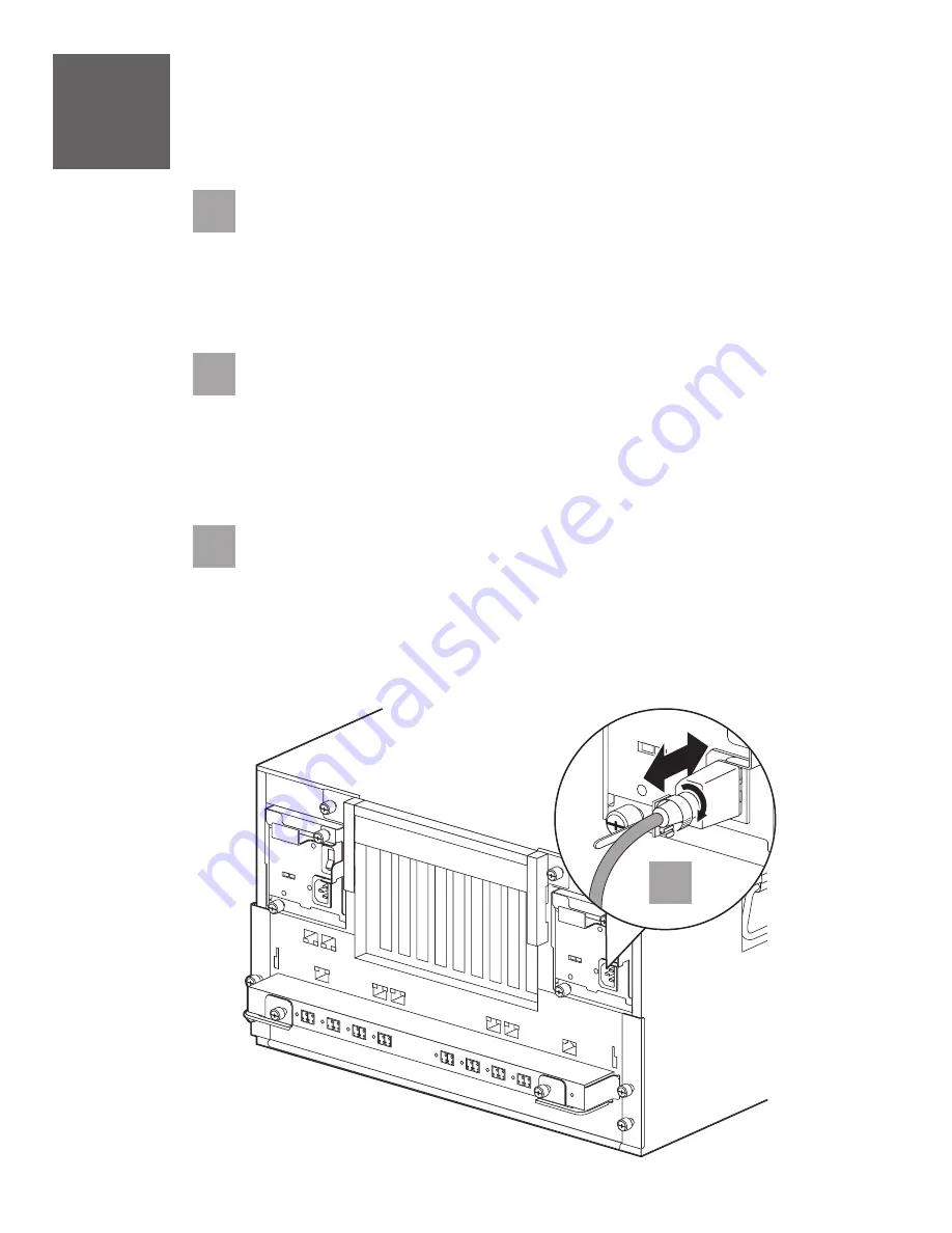
Connect the power cords to all
power receptacles for all storage systems that are being installed
using power cord retainer clips as shown below.

power supply 1 and power supply 2

6.2

Connect the power cords to the power sources, making sure that the

This ensures

redundant power.

power supplies on the left and right sides of the system are connected
to separate and independent AC power sources.

Caution:

Do not power on the system at this time.

6.3

Give all documentation (including this document) and all hardware to the
customer.

6.1

Note:

Refer the customer to the next two pages for additional

planning and setup information.

13

Summary of Contents for N7700

Page 1: ...N7000 Series Gateway Installation and Setup Instructions IBM System Storage ...

Page 2: ......

Page 3: ...y NFS client Where is the NAS system located Text string Do you want to run DNS resolver Do you want to run NIS client Would you like to configure the RLM LAN interface y RLM IP Address RLM Netmask RLM Gateway IP Address Would you like to enable DHCP on the RLM LAN interface y Enter the name or IP address of the mail host Below is a copy of the system setup worksheet If a worksheet has not yet bee...

Page 4: ......

Page 5: ...Series Hardware and Service Guide Need help If you encounter any difficulties while setting up your system contact IBM service and support for assistance Information can also be found at the following Web site www ibm com storage support nas Read the safety notices Before continuing make sure that you have reviewed the safety notices on the documentation CD that came with this system Do not plug a...

Page 6: ...fic models Note Lift box from crate The contents will remain in place Note Eight Small Form Factor Pluggable SFP modules will either be in the accessory box or will be installed on the fiber ports of the gateway system Accessory kit IBM rail kit Power cable DB 9 to RJ 45 console adapter Cable management tray Serial null modem cable N7700 N7900 gateway system ...

Page 7: ...t one envelope with the software EULA and license keys 2 N7700 N7900 1 Console adapter RJ 45 to DB 9 2 IBM rail kit 1 Serial null modem cable 2 Cable management tray 2 ESD wrist strap 4 Power cords 1 Publications There will also be at least one envelope with the software EULA and license keys N7700 2866 A21 N7900 2867 A21 32 kg 70 5 lb 3 Caution The weight of this part or unit is between 32 and 55...

Page 8: ...d that the N7700 N7900 be placed in the lowest position available in a rack For example Gateway 2 Gateway 1 N7700 N7900 N7700 N7900 A21 A21 Model A11 Model A21 Expansion Unit 2 Expansion Unit 1 Filer 2 Loop 1 Filer 2 Loop 1 Expansion Unit 2 Expansion Unit 1 Filer 1 Loop 1 Filer 1 Loop 1 Expansion Unit 4 Expansion Unit 3 Expansion Unit 2 Expansion Unit 1 ...

Page 9: ...line up with the bottom EIA boundary When installed each N7700 N7900 unit will occupy a 6U space Using two silver pan head M5 screws attach the rail to the front of the rack using holes H2 and H8 Tighten the screws with a screwdriver Note 2 3 At the rear of the rack position the rail at the same EIA location used in step 2 2 make sure that the locating pins seat properly Using two silver pan head ...

Page 10: ...if you are installing a second N7700 N7900 Section of rack EIA rail H2 H1 H3 H4 H5 H6 H7 H8 H9 Locating pins Bottom rail screws REAR Left and Right Rails Chassis attach screw H2 H1 H3 H4 H5 H6 H7 H8 H9 FRONT Left and Right Rails Top rail screws Locating pins Chassis attach screw 1 EIA unit 1U ...

Page 11: ... the system unit 2 Power supplies 5 Fan modules Bezel 2 3 2 Carefully remove the front bezel of the N7700 N7900 gateway by pulling out on the semi circular openings on either side of the bezel Caution The weight of this part or unit is between 32 and 55 kg 70 5 and 121 2 lb It takes three persons to safely lift this part or unit C010 ...

Page 12: ...e that you support the fan with your free hand After removing each fan place it on a table or other safe place 3 4 Remove the two power supplies from the rear of the system unit by performing the following steps 1 Loosen the two thumbscrews on the power supply 2 Lower the cam handle and slide the power supply out of the chassis Make sure that you support the power supply with your free hand After ...

Page 13: ...ateway system unit by performing the following steps 1 Align the edges of the power supply with the opening in the system chassis and gently push the power supply into the chassis until the cam handle begins to rise 2 Push the cam handle to the closed position 3 Tighten the two thumbscrews on the power supply Replace the five fan modules at the front of the system unit by performing the following ...

Page 14: ...rear of the rack attach the rear tie down bracket in the orientation shown to the rails using four M5 flat head screws The tie down bracket should be over the rear of the system unit Tie down bracket M5 flat head screws ...

Page 15: ...1 go to step 6 on page 13 If you are installing a model A21 go to step 5 on page 12 4 2 4 2 I0I0 0a 0b 0c 0d 0e 0f 0g 0h RLM e0e e0f e0a e0b e0c e0d 11 4 4 4 1 4 2 Install your cable management tray by inserting one arm into the chassis as shown Then press the other arm towards the center of the chassis and insert it in the slot so that it locks into place 11 ...

Page 16: ...eight 5 1 1 Plug one end of the cluster cable into one of gateway 1 s cluster adapter ports Then plug the other end into gateway 2 s corresponding cluster adapter port You must not cross cable the cluster interconnect adapter Cable the gateway1 ports only to the identical ports on the gateway 2 node 5 1 2 Repeat step 5 1 1 for the remaining port on the cluster adapter 5 1 3 Gently pull on the cabl...

Page 17: ...wn below power supply 1 and power supply 2 6 2 Connect the power cords to the power sources making sure that the This ensures redundant power power supplies on the left and right sides of the system are connected to separate and independent AC power sources Caution Do not power on the system at this time 6 3 Give all documentation including this document and all hardware to the customer 6 1 Note R...

Page 18: ...figuration rules for setting up the storage subsystem Determining whether to use SyncMirror for additional RAID level data protection Creating a document that shows the desired logical configuration between the gateways and storage subsystems Introduction and Planning Guide Planning task Refer to the following Interoperability Matrix Gateway Implementation Guide Configuration diagrams for the stor...

Page 19: ...dia type Installing an NFS or a CFS license Installing the Data ONTAP software Configuring Data ONTAP features that you want to use with your gateway Setup task Refer to the following Gateway Implementation Guide for your storage subsystem type Gateway Implementation Guide for your storage subsystem type Gateway Implementation Guide for your storage subsystem type Gateway Software Setup Installati...

Page 20: ...s publication to IBM products or services do not imply that IBM intends to make them available in every country or region IBM the IBM logo and System Storage are trademarks or registered trademarks of International Business Machines Corporation Data ONTAP SyncMirror NetApp and Network Appliance are trademarks and or registered trademarks of Network Appliance Inc in the United States and other coun...

Reviews: