background image

10

Hardware components


System LED 
definitions

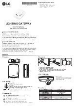
The system LEDs provide information about the overall system status, fan status, 
and power-supply status. The following figure identifies each system LED:

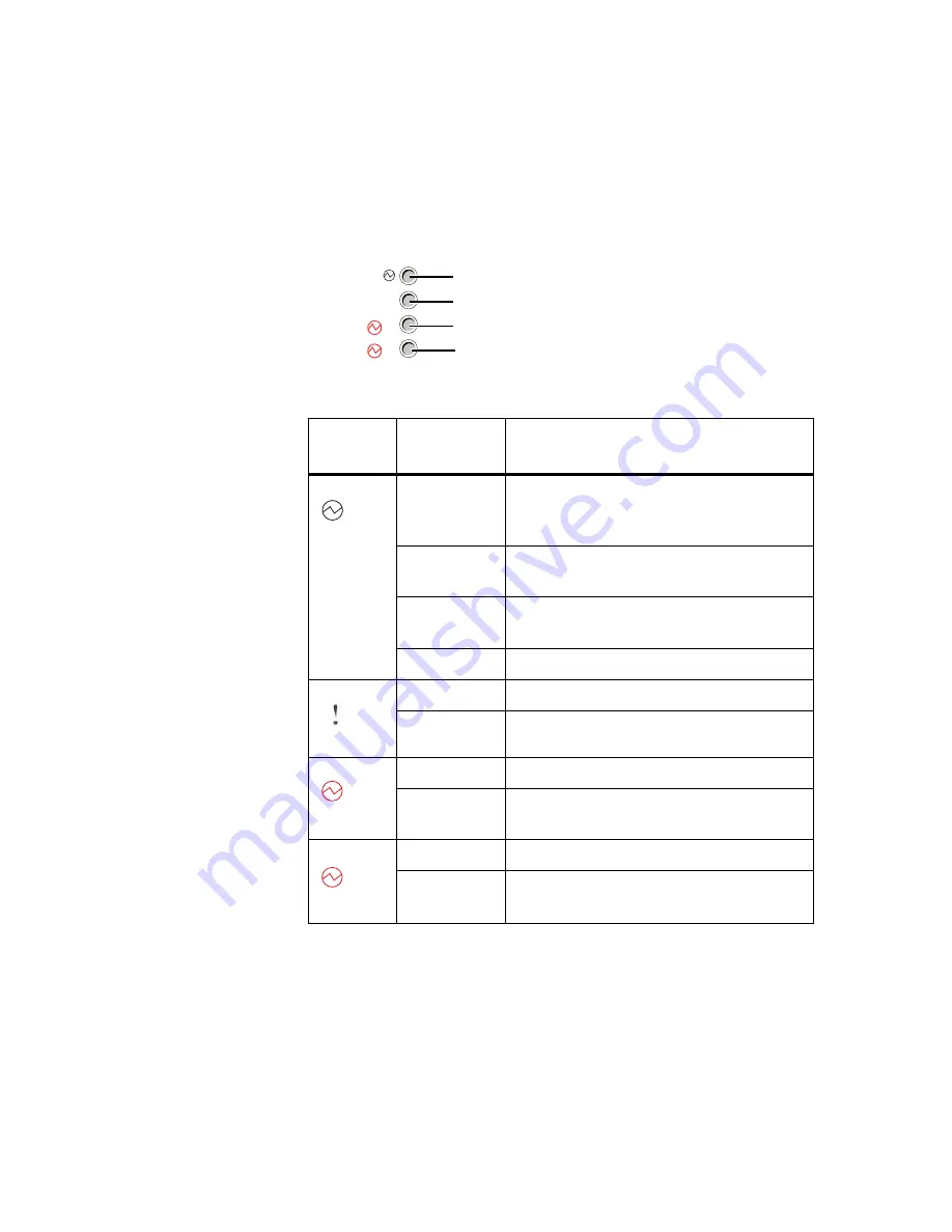
The following table describes the system LEDs:

System 
LEDs

Color

Description

OK

Solid green

The switch DC power (all low-voltage 
supplies from 3.3 to 1.0V except the standby 
DC voltage) is operating normally.

Blinking 
green

The switch is booting, and power-on self test 
(POST) is in progress.

Blinking 
amber

The switch has experienced one or more DC 
power faults.

Off

A standby DC fault is detected.

Fault

Solid amber

One or more fan failures have occurred.

Off

The fans are operating normally.

PWR1

Solid amber

Power supply 1 has a fault or is missing.

Off

Power supply 1 is present and operating 
normally.

PWR2

Solid amber

Power supply 2 has a fault or is missing.

Off

Power supply 2 is present and operating 
normally.

!

1

2

OK

Fault

PWR1

PWR2

1

2

Summary of Contents for N Series

Page 1: ...IBM System Storage N series 10G Cluster Mode Switch Installation Guide GI13 2866 00 NA 210 06282_B0 ...

Page 2: ...TWARE EVEN IF ADVISED OF THE POSSIBILITY OF SUCH DAMAGE NetApp reserves the right to change any products described herein at any time and without notice NetApp assumes no responsibility or liability arising from the use of products described herein except as expressly agreed to in writing by NetApp The use or purchase of this product does not convey a license under any patent rights trademark righ...

Page 3: ...apCopy SnapDirector SnapDrive SnapFilter SnapLock SnapManager SnapMigrator SnapMirror SnapMover SnapRestore Snapshot SnapSuite SnapValidator SnapVault StorageGRID StoreVault the StoreVault logo SyncMirror Tech OnTap The evolution of storage Topio vFiler VFM Virtual File Manager VPolicy WAFL and Web Filer are trademarks or registered trademarks of NetApp Inc in the United States other countries or ...

Page 4: ... local law INTERNATIONAL BUSINESS MACHINES CORPORATION PROVIDES THIS PUBLICATION AS IS WITHOUT WARRANTY OF ANY KIND EITHER EXPRESS OR IMPLIED INCLUDING BUT NOT LIMITED TO THE IMPLIED WARRANTIES OF NON INFRINGEMENT MERCHANTABILITY OR FITNESS FOR A PARTICULAR PURPOSE Some states do not allow disclaimer of express or implied warranties in certain transactions therefore this statement may not apply to...

Page 5: ... non IBM products was obtained from the suppliers of those products their published announcements or other publicly available sources IBM has not tested those products and cannot confirm the accuracy of performance compatibility or any other claims related to non IBM products Questions on the capabilities of non IBM products should be addressed to the suppliers of those products If you are viewing...

Page 6: ...vi 10G Cluster Mode Switch Installation Guide ...

Page 7: ...chnical specifications 18 Chapter 2 Hardware Installation 21 Before you begin 22 Installing the switch 24 Connecting to ports and power 28 Installing and removing hardware components 30 Chapter 3 Switch Management 33 Accessing the management interface 34 Boot process 42 Startup Utility functions 45 Glossary 47 Index 51 ...

Page 8: ...2 Table of Contents ...

Page 9: ...nventions The following conventions may be used in this document Additional documentation The following documentation provides additional information about the CN1610 u The CN1610 Network Switch CLI Command Reference describes the commands available from the command line interface CLI for managing monitoring and configuring the switch u The CN1610 Network Switch Administrator s Guide contains step...

Page 10: ...4 About this guide ...

Page 11: ...16 10 Gigabit Small Form Factor Pluggable Plus SFP ports The switch includes redundant power supplies and fan trays that support hot swapping for high availability This 1U switch can be installed in a standard 19 inch IBM N series 42U system cabinet or third party cabinet The switch supports local management through the console port or remote management by using Telnet or SSH through a network con...

Page 12: ...ter network switch v Customer LAN u Remote management port u Console port u AC power sockets u System and port LEDs The following figure shows the rear panel of the switch The front panel provides access to the power supplies and fan trays 1 2 SPD LNK SPD LNK 1 2 3 4 5 6 7 8 9 10 11 12 13 14 15 16 AC Power Socket 1 Switch Ports AC Power Socket 2 System LEDs Port LEDs Management Port ISL Ports Seri...

Page 13: ... is segregated from operational network traffic on the switch ports and cannot be switched or routed to the operational network Console port The console RJ45 port is used only for management through a serial interface This port provides a direct connection to the switch and allows you to access the CLI from a console terminal connected to the port through the provided serial cable RJ45 to female D...

Page 14: ...ivity LED is on the upper right side of the port The following table describes the Speed and Link Activity LEDs found above each SFP port SFP port LED Color Description Speed Solid green A valid 10 Gbps link is established on the port Off No link or a valid 1 Gbps link is established on the port Link Activity Solid green A valid link is established on the port Blinking green The port is transmitti...

Page 15: ...immediately to maintain redundancy If one power supply fails a second power supply must be present and functional for the switch to continue to operate Fan units The two fan trays in the CN1610 support hot swapping and can be removed or inserted from the front panel Each fan tray includes two fans For the switch to maintain an acceptable operating temperature both fan trays must be present in the ...

Page 16: ...andby DC voltage is operating normally Blinking green The switch is booting and power on self test POST is in progress Blinking amber The switch has experienced one or more DC power faults Off A standby DC fault is detected Fault Solid amber One or more fan failures have occurred Off The fans are operating normally PWR1 Solid amber Power supply 1 has a fault or is missing Off Power supply 1 is pre...

Page 17: ...ch each fan tray and power supply includes LEDs on the front panel to provide status information Front panel LEDs Color Description AC OK Solid green The AC power supply has power Off The AC power supply does not have power Fan Amber A fan fault has been detected Off The fan is operating normally ...

Page 18: ...information such as an IP address for the management interface from a BootP or DHCP server on the network SNTP client Synchronize the time on the switch with a remote SNTP server The switch supports SNTP Version 4 DNS client Specify the DNS server to use to resolve host names to IP addresses Dual image support Store up to two software images and two configuration files on the switch flash file sys...

Page 19: ...Pingv6 u Traceroutev6 u TFTP u SSH u SSL u TELNET u SNMP Logging Maintain a record locally on the switch or on a remote Syslog server of switch events including CLI commands executed on the switch Control the severity of messages to log System monitoring View information about the system temperature power supply and fan status Remote monitoring RMON The switch supports the following four groups de...

Page 20: ...tic addresses or clear the L2FDB and control the number of entries that can be dynamically learned Layer 2 multicast forwarding database MFDB control Limit multicasts to only certain ports in the switch to prevent traffic from going to parts of the network where that traffic is unnecessary VLANs Optimize network traffic patterns by creating VLANs and configuring member ports so that broadcast mult...

Page 21: ...ses CDP IEEE 802 1AX link aggregation Increase bandwidth between two switches by aggregating multiple ports in one logical Link Aggregation Group LAG which is also known as a port channel The switch treats the LAG as if it were a single link The switch supports both static and dynamic LAGs IEEE 802 1s Multiple Spanning Tree MSTP Prevent and resolve L2 forwarding loops by using MSTP to map VLANs to...

Page 22: ...m flooding other parts of the network Switching feature Description QoS Feature Description Class of Service CoS queuing Directly configure certain aspects of the hardware traffic queueing to affect QoS behavior for different types of network traffic CoS queue characteristics such as minimum guaranteed bandwidth and transmission rate shaping are configurable at the queue or port level IP Access Co...

Page 23: ...fy the authentication method for different access types Denial of Service DoS protection Provide protection against DoS attacks on the switch and on the network IEEE 802 1X port based access control Prevent unauthorized devices from accessing the network through the switch on a per port basis RADIUS client Allow the switch to communicate with a network RADIUS server to authenticate users prior to ...

Page 24: ...EE 802 3x Flow Control u IEEE 802 3ab 1000Base T u IEEE 802 3z 1000Base X u IEEE 802 3ae 10 Gpbs Ethernet over fiber Environmental specification The following table lists the environmental specification for the CN1610 switch Specification Measurement Height 43 mm 1 69 in Width 445 mm 17 5 in Depth 508 mm 20 in Weight 10 2 kg 22 5 lbs Specification Measurement Operating temperature 10 to 40 C Stora...

Page 25: ...wer specifications The following table lists the power specifications for the CN1610 switch Specification Measurement AC input frequency universal 50 to 60 Hz AC input voltage universal 100 to 240 VAC Power supply 300W DC output voltage 12V ...

Page 26: ...20 Technical specifications ...

Page 27: ...all the CN1610 hardware and provides step by step instructions about installing and powering on the switch Topics in this chapter This chapter includes the following topics u Before you begin on page 22 u Installing the switch on page 24 u Connecting to ports and power on page 29 u Installing and removing hardware components on page 31 ...

Page 28: ... exceed 328 feet 100 meters u The cable length from the SFP ports must not exceed recommended lengths for the cable and transceiver module type u The ventilation holes on the front and rear panels must not be obstructed in order to provide proper airflow through the switch u The cabling must be routed away from sources of electrical interference such as power lines and fluorescent lighting fixture...

Page 29: ...kit Required tools and equipment Before installing the switch in a standard equipment rack or IBM N series 42U System Cabinet make sure you have the following equipment u Number 2 Phillips screwdriver u Two standard rack screws u Electrostatic discharge ESD wrist strap u Cage nut installation tool Description Quantity Support rails 2 left and right M5 screws 10 M5 nut clips 10 10 32 screws 2 ...

Page 30: ...42 four post rack 1 Fix three clip nuts to the front rack and two one to the top and the other to the bottom hole of the rear rack Fix the clip nuts to both the left and the right racks The diagram below shows the four post rack and the clip nuts that are to be clamped sideways onto the flanges of the rack The table below lists the label descriptions for the diagram Label Description 1 The flanges...

Page 31: ... of the nut clip that must be on the inner side of the flange after the nut clip is clamped sideways onto the flange 2 The nut clips to be clamped sideways onto the flanges of the rack 3 The rear portion of the rack 4 The front portion of the rack Label Description n6200030 ...

Page 32: ...e descriptions for each label in the diagram 3 Slide the switch onto the supporting rails until the support brackets on both sides of the switch touch the front flanges Fix the front side of the switch to the rails by using two M5 screws Label Description 1 The rear portion of the rack 2 The front portion of the rack 3 The M5 screws used to fix the rails onto the rack n6200027 1 2 3 3 3 3 ...

Page 33: ...ll seated Use two 10 32 screws one for each side to fix the rear end of the switch to the tie down feature on the rail The diagram below is of a left rail Label Description 1 The rear portion of the rack 2 The front portion of the rack 3 The M5 screws used to fix the front side of the switch to the rails n6200028 1 2 3 3 n6200029 1 ...

Page 34: ...iption for the label in the diagram The illustration below displays the alignment of the rear bracket with the tie down hole The arrow indicates where the 10 32 screw must be fitted in Label Description 1 The location of the tie down feature on the left rail ...

Page 35: ...e connection Note The cable length between the switch and the attached device is limited to 100m 328 ft When a link is established between the switch and the connected device the link LED is green Connecting to the SFP ports SFP copper twin ax cables connect directly into the SFP port and do not require a separate SFP transceiver module If you use an optical cable for 10GBase SR transmissions inst...

Page 36: ...ach power supply connect the end of the power cable to the power receptacle on the rear panel of the switch Note The built in power cables on the power supply front panels should always be connected 2 Connect the power cord to the power source 3 Verify that the AC OK LED on each power supply is green Connecting to the console port The console port uses an RJ45 connector for serial communication to...

Page 37: ... Align the module with the port 3 Insert the module securely into the SFP port until it clicks into place in the rear of the slot Use minimal pressure when inserting the transceiver to avoid damage To remove the SFP module disconnect the cable from the module and gently but firmly pull it out of the port Removing and installing a power supply The switch is intended to operate with both power suppl...

Page 38: ...roviding power to the switch Removing and installing a fan tray For the switch to maintain an acceptable operating temperature the four fans two in each fan tray must be operational If any fan fails the fault LED on the rear panel of the switch is amber and the fan tray with the failed fan must be replaced CAUTION If any fan unit fails replace the fan tray immediately to ensure that the switch ope...

Page 39: ...g the switch command line interface and performing boot menu functions For information about configuring switch features see the CN1610 Network Switch CLI Command Reference and the CN1610 Network Switch Administrator s Guide Topics in this chapter This chapter includes the following topics u Accessing the management interface on page 34 u Boot process on page 42 u Startup Utility functions on page...

Page 40: ...or out of band switch management This 10 100 1000Base T port is known as the remote management port or service port Traffic received on the remote management port is never switched to any in band network port Likewise traffic received on any in band port is never forwarded or routed over the remote management port Alternatively you may choose to manage the switch through the production network Thi...

Page 41: ...agement port and enable the DHCP client on the network ports Connecting to the CLI by using the console port To access the CLI by using the console port follow these steps 1 Using the supplied RJ45 to DB 9 console cable connect a VT100 ANSI terminal or a workstation to the console serial port If you attached a PC Apple or UNIX workstation start a terminal emulation program such as HyperTerminal xt...

Page 42: ...net mask and default gateway The procedures in this section describe how to view network information configured on the remote management port and optionally enable the DHCP BootP or DHCPv6 client if necessary For information about similar procedures to allow the switch to be managed over the production network see Enabling the DHCP or BootP client for in band management on page 39 To view the mana...

Page 43: ...BootP enter the following command from Privileged EXEC mode serviceport protocol bootp v To enable the DHCPv6 client on the switch enter the following command serviceport ipv6 address dhcp 4 Optionally save the current configuration so that all changes are retained during a switch reset write memory Configuring static networkinformation on the remote management port Use the following procedures to...

Page 44: ...ent interface with an IPv6 address prefix of 2001 DB8 132 3 32 and a default gateway of 2001 DB8 132 1 32 enter the following commands serviceport ipv6 address 2001 DB8 132 3 32 serviceport ipv6 gateway 2001 DB8 132 1 5 To verify the configured information enter the following command CN1610 show serviceport Interface Status Up IP Address 192 168 2 23 Subnet Mask 255 255 255 0 Default Gateway 192 1...

Page 45: ... console port and enter Privileged EXEC mode as described in Connecting to the CLI by using the console port on page 35 2 Enable the DHCP or BOOTP client on the switch v To enable DHCP enter the following command from Privileged EXEC mode network protocol dhcp If the command is not available make sure you are in Privileged EXEC mode In Privileged EXEC mode the switch hostname is in parentheses fol...

Page 46: ...on the remote management port on page 37 1 Access the switch CLI by using the console port and enter Privileged EXEC mode as described in Connecting to the CLI by using the console port on page 35 2 Optionally to clear any existing IP address information and set the address configuration mode to static enter network parms none network protocol none 3 To configure the static IP address subnet mask ...

Page 47: ...168 2 23 Subnet Mask 255 255 255 0 Default Gateway 192 168 2 1 IPv6 Administrative Mode Enabled IPv6 Prefix is fe80 210 18ff fe82 64c 64 IPv6 Prefix is 2001 DB8 132 3 32 IPv6 Default Router is 2001 DB8 132 1 Burned In MAC Address 00 10 18 82 06 4C Locally Administered MAC address 00 00 00 00 00 00 MAC Address Type Burned In Configured IPv4 Protocol None Configured IPv6 Protocol None DHCPv6 Client ...

Page 48: ...ns on page 45 To boot the switch and access the Startup Utility menu follow these steps 1 Connect to the switch through the console port and set the terminal settings appropriately as described in Connecting to the CLI by using the console port on page 35 2 Start the boot process by using one of the following methods v If the switch is powered on and operational reset the switch by entering the fo...

Page 49: ...artup For information about the options available from the menu see Startup Utility functions on page 45 Next steps At the end of the boot process the switch loads the saved configuration When the process has successfully completed the User login prompt appears To enter User EXEC mode enter admin which is the default user and press Enter at the password prompt The admin user does not have a passwo...

Page 50: ...44 Boot process For information about configuring switch features see the CN1610 Network Switch CLI Command Reference and the CN1610 Network Switch Administrator s Guide ...

Page 51: ...le to use option 2 Load Code Update Package to load a new image onto the switch After you erase permanent storage you must download an image to the switch otherwise the switch will not be functional Select Boot Method Use option 4 to specify whether the system should boot from the image stored on the internal flash from an image over the network or from an image over the serial port By default the...

Page 52: ... boot cycle with the newly active image After you activate the backup image the following information appears Image image1 is now active Code update instructions found Extracting kernel and rootfs from image1 Copying kernel rootfs uimage to boot flash area Activation complete image1 activated system reboot recommended Reboot Y N Enter y to reload the switch Start Diagnostic Application Option 6 is...

Page 53: ...d Internal Spanning Tree CLI Command Line Interface DHCP Dynamic Host Configuration Protocol DSCP Differentiated Services Code Point EAP Extensible Authentication Protocol EAPOL EAP over LAN GARP Generic Attribution Registration Protocol giaddr This field indicates the relaying gateway in a DHCP packet GVRP GARP VLAN Registration Protocol ...

Page 54: ...s the port that mirrors to probe Mirroring Port Destination Mirror Port MDIX Management Dependent Interface Crossover Monitor Port Destination Mirror Port that is the port with probe attached MSTP Multiple Spanning Tree Protocol NIM Network Interface Manager PAE Port Access Entity Probe port Destination Mirror Port that is the port with probe attached QoS Quality of Service ...

Page 55: ...ion Dial In User Service RSTP Rapid Spanning Tree Protocol SNTP Simple Network Time Protocol SSH Secure Shell STP Spanning Tree Protocol TACACS Terminal Access Controller Access Control System TDR Time Domain Reflectometry VLAN Virtual LAN ...

Page 56: ...50 Glossary ...

Page 57: ... connecting to 29 location 6 contents package 22 conventions document 3 CoS 16 D depth chassis 18 DHCP client enabling 39 remote management port 36 diagnostic application starting 46 dimentions switch 18 direct attach cables 7 document conventions 3 dot1x 17 dual image 12 E environmental specification 18 erase current configuration 45 erase permanent storage 45 F fan tray removing and installing 3...

Page 58: ...4 modes command 43 MSTP 15 MTU 14 N network information configuring 35 O outlet power 29 out of band management 34 P package contents 22 password default 35 permanent storage erasing 45 port console 7 29 LED definitions 8 mirroring 15 remote management 7 RJ 45 28 service 34 SFP 7 28 port channels 15 POST 42 power connecting 29 controlling 29 power specification 19 power supply 9 removing and insta...

Page 59: ...18 SSH 12 34 standards IEEE 802 3 18 Startup Utility functions 45 menu accessing 42 static IP address 37 40 switching features 14 system features 12 system LED definitions 10 T TACACS client 17 technical specifications 18 telnet 12 34 temperature operating 18 storage 18 terminal VT100 ANSI 29 terminal emulation settings 35 terms definitions 3 TFTP 12 tools and equipment installation 23 transceiver...

Page 60: ...54 Index ...

Page 61: ......

Page 62: ... NA 210 06282_B0 Printed in USA GI13 2866 00 ...

Reviews: