background image

Manual LPCI-COM-8SM 

14

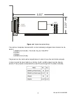
Other jumpers 

1) RS 485 (2 wire mode) - Two jumpers must be installed for each channel in this mode in order 
to connect the output and input lines. These jumpers are located near the cable connector and 
are labeled with the channel letter and “485.” 
2) RS 485 (2 wire mode) using “Auto RTS” - One jumper must be installed for each channel in 
this mode. This jumper is located at the end of the card away from the cable connector, 
adjacent to the “M” jumpers and are labeled with the channel letter and “A8". 
3) RS 485 or RS 422 Loads - One jumper must be installed for each channel which requires a 
load. This jumper is located at the cable connector end of the card and is labeled with the 
channel letter and “LD.” 


Notes

1) Any unneeded jumpers that are installed can cause the card to function incorrectly. 
2) If the “Auto RTS” jumpers are changed, the card should be rebooted or reset. This is required 
because the status of the jumpers is read when the card is reset and is used to program the 
Auto RTS function into the appropriate channel(s) of the UART. If the state of this jumper is 
changed, the UART will not be properly programmed until the jumper has been reread. To do 
this, the card must be reset. 

Summary of Contents for LPCI-COM-8SM

Page 1: ...go CA 92121 858 550 9559 FAX 858 550 7322 contactus accesio com www accesio com MODEL LPCI COM 8SM LPCI COM 4SM LPCI COM232 8 LPCI COM232 4 Low Profile PCI Multi Port Serial Communications Cards USER...

Page 2: ...S nor the rights of others IBM PC PC XT and PC AT are registered trademarks of the International Business Machines Corporation Printed in USA Copyright 2004 2005 by ACCES I O Products Inc 10623 Rosell...

Page 3: ...parts not excluded by warranty Warranty commences with equipment shipment Following Years Throughout your equipment s lifetime ACCES stands ready to provide on site or in plant service at reasonable...

Page 4: ...implified Termination Schematic 11 Data Cable Wiring 11 Baud Rate Ranges 12 Interrupts 12 Table 3 1 WindowsNT Registry Values 12 Figure 3 2 Option Selection Map 13 Other jumpers 14 Chapter 4 Address S...

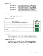
Page 5: ...and RX Supports data communication speeds up to 921 6kbps Software compatible with all operating systems 6 breakout cable terminating with industry standard DB9M connectors Applications POS Point of s...

Page 6: ...against lost data in multitasking operating systems while maintaining 100 percent compatibility with the original IBM serial port The system assigns the address es A crystal oscillator is located on t...

Page 7: ...etion of the transmission of the character default or can be set to wait up to one additional character s transmission time after data transfer is complete and then disabled The receiver is therefore...

Page 8: ...es BRKT 551 SCB Strengthening bracket for use with standard height PCI bracket only ADAP9 Screw terminal adaptor DB9F to 9 screw terminals ADAP9 2 Screw terminal adaptor with two DB9F connectors and 1...

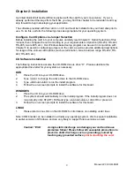
Page 9: ...5 etc CD Software Installation The following instructions assume the CD ROM drive is drive D Please substitute the appropriate drive letter for your system as necessary DOS 1 Place the CD into your CD...

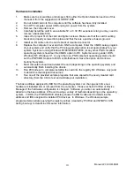
Page 10: ...DOS Windows NT Windows 3 1 or any other non PNP compliant operating system should set the PNP CMOS option to BIOS or Motherboard Save the option and continue booting the system 9 Most computers shoul...

Page 11: ...nel are located near the output connector They are labeled by channel The load jumper is labeled LD The other two jumpers are used to connect the transmit and receive lines for the two wire RS485 mode...

Page 12: ...d to use address 0xFC00 with an interrupt of 05 the values in the Registry are Serial2 subkey PortAddress REG_DWORD 0xFC00 Interrupt REG_DWORD 5 DosDevices REG_SZ COM3 InterruptStatus REG_DWORD 0xFC40...

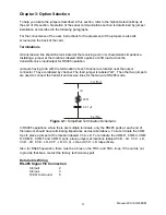
Page 13: ...485 2 wire mode This mode may use Auto RTS 2 RS422 3 RS232 4 RS485 4 wire mode The jumpers on the card must be properly placed in order to have the card function properly In order to select the basic...

Page 14: ...tter and A8 3 RS 485 or RS 422 Loads One jumper must be installed for each channel which requires a load This jumper is located at the cable connector end of the card and is labeled with the channel l...

Page 15: ...etected on the PCI bus the addresses assigned to each function on each of the cards and the respective IRQs if any allotted Alternatively some operating systems Windows 95 98 2000 XP can be queried to...

Page 16: ...ndows Programming The card installs into Windows as COM ports Thus the Windows standard API functions can be used In particular CreateFile and CloseHandle for opening and closing a port SetupComm SetC...

Page 17: ...4 addresses The interrupt status register is located at base 40h Baud Rates On the card the UART clock frequency is 1 8432 MHz Below is a table of popular divisor frequencies Baud Rate Divisor x1 Divi...

Page 18: ...iques cable connect to chassis ground at the aperture shielded twisted pair wiring etc be used for the input output wiring DB 9 Male Pin for each of Ch A G RS 232 Signals Industry Standard RS 485 Sign...

Page 19: ...s used are specified as capable of 1Mbps The highest baud rate achievable using the standard oscillator and divisor is 921 6kbps Address Continuously mappable within 0000 to FFFF hex range of PCI bus...

Page 20: ...l all receive Balanced Differential Signals The reason that RS422 and RS485 devices can drive longer lines with more noise immunity than RS232 devices is that a balanced differential drive method is u...

Page 21: ...Mode Voltage Range 7V Receiver Input Resistance 4K Table A 2 RS422 Specification Summary To prevent signal reflections in the cable and to improve noise rejection in both the RS422 and RS485 mode the...

Page 22: ...lowing illustration shows a typical multidrop or party line network Note that the transmission line is terminated on both ends of the line but not at drop points in the middle of the line Figure A 1 T...

Page 23: ...5 2 1 5 9 13 17 21 25 29 3 2 6 10 14 18 22 26 30 4 3 7 11 15 19 23 27 31 5 331 331 331 331 672 672 672 672 6 38 42 46 50 54 58 62 66 7 35 39 43 47 51 55 59 63 8 36 40 44 48 52 56 60 64 9 4 8 12 16 20...

Page 24: ...anual or just want to give us some feedback please email us at manuals accesio com Please detail any errors you find and include your mailing address so that we can send you any manual updates 10623 R...

Reviews: