background image

1. Read the safety information that begins on page and “Installation guidelines”

on page 24.

2. Turn off the server and peripheral devices and disconnect the power cords and

all external cables.

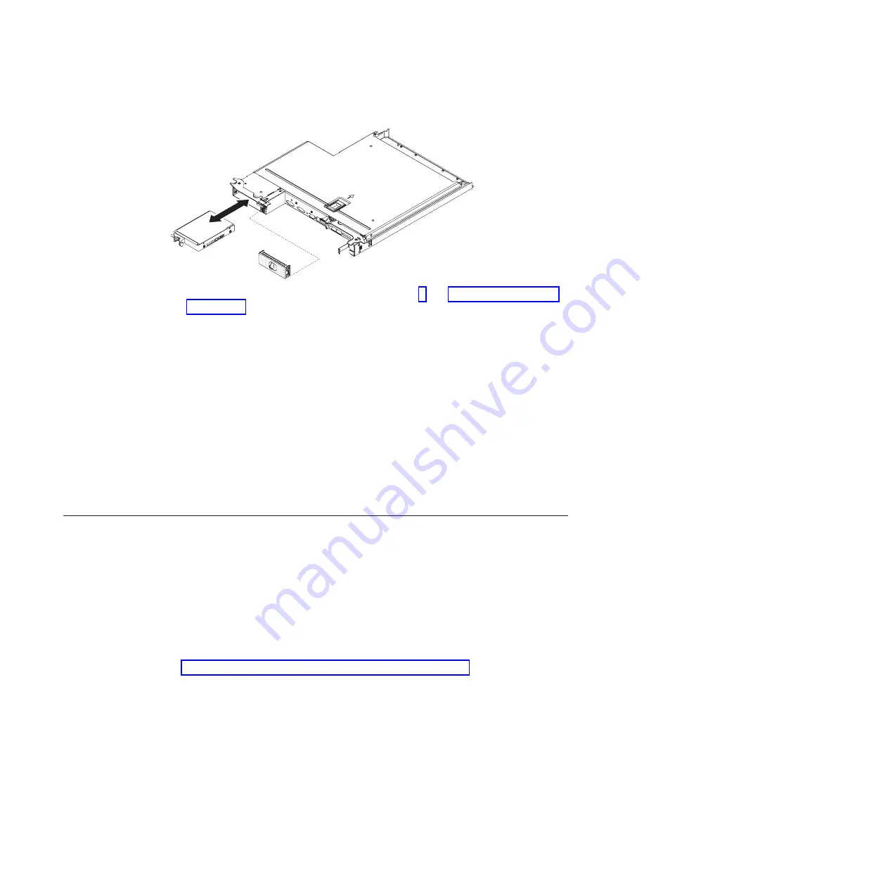
3. Remove the filler panel from the empty drive bay by pulling straight out on the

blue touch point.

4. Touch the static-protective package that contains the drive to any unpainted

metal surface on the server; then, remove the drive from the package and place
it on a static-protective surface.

5. Install the hard disk drive in the drive bay:

a. Grasp the black drive handle and slide the blue release latch to the right

and align the drive assembly with the guide rails in the bay.

b. Gently push the drive into the bay until the drive stops.

6. Reinstall the drive bay filler panel that you removed earlier.

7. If you are installing additional simple-swap hard disk drives, do so now.

Installing a memory module

The following notes describe the types of DIMMs that the server supports and other
information that you must consider when you install DIMMs.

v

When you install or remove DIMMs, the server configuration information
changes. When you restart the server, the system displays a message that
indicates that the memory configuration has changed.

v

The server supports only industry-standard double-data-rate 3 (DDR3), 800,
1066, or 1333 MHz, PC3-6400, PC3-8500, or PC3-10600 registered or
unbuffered, synchronous dynamic random-access memory (SDRAM) dual inline
memory modules (DIMMs) with error correcting code (ECC). See
http://www.ibm.com/servers/eserver/serverproven/compat/us/ for a list of
supported memory modules for the server.

– The specifications of a DDR3 DIMM are on a label on the DIMM, in the

following format.

ggggg eRxff

PC3

v

-

wwwwwm

-

aa

-

bb

-

ccd

where:

ggggg

is the total capacity of the DIMM (for example, 256MB, 512MB,

1GB, 2GB, or 4GB)

eR

is the number of ranks

1R = single-rank

2R = dual-rank

30

System x iDataPlex dx360 M4 Types 7918 and 7919: User’s Guide

Summary of Contents for iDataPlex dx360 M4

Page 1: ...System x iDataPlex dx360 M4 Types 7918 and 7919 User s Guide...

Page 2: ......

Page 3: ...System x iDataPlex dx360 M4 Types 7918 and 7919 User s Guide...

Page 4: ...ices and User Guide documents on the IBM Documentation CD and the Warranty Information document The most recent version of this document is available at http www ibm com supportportal First Edition Fe...

Page 5: ...send DSA data to IBM 23 Installation guidelines 24 System reliability guidelines 25 Working inside the server with the power on 25 Handling static sensitive devices 26 Removing a system board tray fr...

Page 6: ...ormation from the World Wide Web 55 Software service and support 56 Hardware service and support 56 IBM Taiwan product service 56 Appendix B Notices 57 Trademarks 57 Important notes 58 Particulate con...

Page 7: ...fety Information Avant d installer ce produit lisez les consignes de s curit Vor der Installation dieses Produkts die Sicherheitshinweise lesen Prima di installare questo prodotto leggere le Informazi...

Page 8: ...formation document For example if a caution statement is labeled Statement 1 translations for that caution statement are in the Safety Information document under Statement 1 Be sure to read all cautio...

Page 9: ...sconnect signal cables v Never turn on any equipment when there is evidence of fire water or structural damage v Disconnect the attached power cords telecommunications systems networks and modems befo...

Page 10: ...battery replace it only with the same module type made by the same manufacturer The battery contains lithium and can explode if not properly used handled or disposed of Do not v Throw or immerse into...

Page 11: ...he device v Use of controls or adjustments or performance of procedures other than those specified herein might result in hazardous radiation exposure DANGER Some laser products contain an embedded Cl...

Page 12: ...cal current supplied to the device The device also might have more than one power cord To remove all electrical current from the device ensure that all power cords are disconnected from the power sour...

Page 13: ...eable parts inside these components If you suspect a problem with one of these parts contact a service technician Statement 12 CAUTION The following label indicates a hot surface nearby Statement 14 C...

Page 14: ...ragen werden L014 L014 Statement 26 CAUTION Do not place any object on top of rack mounted devices This server is suitable for use on an IT power distribution system whose maximum phase to phase volta...

Page 15: ...CAUTION Hazardous moving parts are nearby Safety xiii...

Page 16: ...xiv System x iDataPlex dx360 M4 Types 7918 and 7919 User s Guide...

Page 17: ...ver products at http www ibm com systems x At http www ibm com support mysupport you can create a personalized support page by identifying IBM products that are of interest to you From this personaliz...

Page 18: ...s See the Rack Installation Instructions document on the IBM System x Documentation CD for complete rack installation and removal instructions The IBM System x Documentation CD The IBM System x Docume...

Page 19: ...ion To select more than one document press and hold the Ctrl key while you select the documents Click View Book to view the selected document or documents in Acrobat Reader or xpdf If you selected mor...

Page 20: ...include information about those features or technical updates might be available to provide additional information that is not included in the server documentation These updates are available from the...

Page 21: ...of the server Depending on the hardware configuration some features might not be available or some specifications might not apply Racks are marked in vertical increments of 4 45 cm 1 75 inches Each i...

Page 22: ...on the rear to connect to a systems management network This system management connector is dedicated to the IMM2 functions v One serial port Predictive Failure Analysis PFA alerts v Memory v Hard dis...

Page 23: ...ting systems and BIOS based adapters as well as UEFI compliant adapters Note The server does not support DOS Disk Operating System v IBM Dynamic System Analysis Preboot diagnostics programs The Dynami...

Page 24: ...optional hardware devices and provides the correct configuration programs and device drivers For more information about the ServerGuide Setup and Installation CD see Using the ServerGuide Setup and In...

Page 25: ...dicated systems management network or a shared network v TCP IP offload engine TOE support The Ethernet controllers in the server support TOE which is a technology that offloads the TCP IP flow from t...

Page 26: ...N through remote initial program load RIPL or dynamic host configuration protocol boot protocol DHCP BOOTP v System auto configuring from the configuration menu v System error logging POST and IMM2 v...

Page 27: ...g a configuration plan that can apply those settings to multiple systems v Updating installed plug ins to add new features and functions to the base capabilities v Managing the life cycles of virtual...

Page 28: ...12 System x iDataPlex dx360 M4 Types 7918 and 7919 User s Guide...

Page 29: ...ponents and configurations the server controls and light emitting diodes LEDs and how to turn the system board tray on and off System board tray components The following illustration shows the major c...

Page 30: ...icroprocessor System board Power supply paddle card 3 5 inch simple swap backplate 3 5 inch simple swap hard disk drive 3 5 inch filler panel System board tray Dual port network adapter Optional DIMM...

Page 31: ...ormation about the external connectors See the Problem Determination and Service Guide for information about the other system board connectors DIMM 4 1 DIMM 16 13 DIMM 12 5 Microprocessor 1 Internal U...

Page 32: ...te to selected system functions See the Problem Determination and Service Guide for more information about using jumpers on the system board CMOS clear jumper uEFI boot backup jumper TPM physical pres...

Page 33: ...lowing illustration shows a 2U chassis The 2U chassis contains a power supply and a water loop assembly that provide operating power and cooling for all components in the chassis The 2U chassis suppor...

Page 34: ...ws the controls connectors and LEDs on the front of the server The operator panel on the system board tray is the same for all server configurations Power on LED Locator LED Hard disk drive activity L...

Page 35: ...usly Note The maximum video resolution is 1600 x 1200 at 75 Hz v Systems management Ethernet connector Use this connector to connect the server to a network for full systems management information con...

Page 36: ...y 5 seconds after you install the system board tray in a chassis the system board tray is connected to power and the power on button LED will blink quickly Approximately 20 to 40 seconds after the sys...

Page 37: ...of the following ways v You can turn off the system board tray from the operating system if your operating system supports this feature After an orderly shutdown of the operating system the system boa...

Page 38: ...v The integrated management module II IMM2 can turn off the system board tray as an automatic response to a critical system failure 22 System x iDataPlex dx360 M4 Types 7918 and 7919 User s Guide...

Page 39: ...y with the newly installed devices 3 Save the DSA log as a file and send it to IBM For information about transferring data and logs see http publib boulder ibm com infocenter toolsctr v1r0 index jsp t...

Page 40: ...about tools for updating managing and deploying firmware see the ToolsCenter for System x and BladeCenter at http publib boulder ibm com infocenter toolsctr v1r0 index jsp v Before you install option...

Page 41: ...ty make sure that the following requirements are met v Each of the drive bays has a drive or a filler panel and electromagnetic compatibility EMC shield installed in it v If the server has redundant p...

Page 42: ...discharge observe the following precautions v Limit your movement Movement can cause static electricity to build up around you v The use of a grounding system is recommended For example wear an elect...

Page 43: ...tem board tray on the system board then see the Problem Determination and Service Guide for information about how to solve the problem 3 If external cables are connected to the front of the system boa...

Page 44: ...hassis on page 27 4 Carefully set the system board tray on a flat static protective surface with the cover side up 5 Pull up firmly on the blue latch on the top of the system board tray then lift the...

Page 45: ...turn off the system board tray before installing simple swap drives in the system board tray Before you install a simple swap SATA hard disk drive read the following information v Make sure that the d...

Page 46: ...ow Installing a memory module The following notes describe the types of DIMMs that the server supports and other information that you must consider when you install DIMMs v When you install or remove...

Page 47: ...tered DIMM RDIMM U Unbuffered DIMM with no ECC x64 bit primary data bus aa is the CAS latency in clocks at maximum operating frequency bb is the JEDEC SPD Revision Encoding and Additions level cc is t...

Page 48: ...ory and the amount of configured memory run the Setup utility For additional information see Chapter 4 Configuring the server on page 39 v DIMMs in the server must be the same type to ensure that the...

Page 49: ...r and have no matching requirements Table 3 Non mirroring normal mode DIMM installation sequence Number of installed microprocessor DIMM connector population sequence One microprocessor installed 1 3...

Page 50: ...close the clips gently Retaining clip DIMM Water loop 7 Orient the DIMM so that the DIMM keys align correctly with the connector on the system board 8 Insert the DIMM into the connector by aligning t...

Page 51: ...ps 1 Read the safety information that begins on page v and Installation guidelines on page 24 2 Turn off the server and peripheral devices and disconnect the power cords 3 Remove the cover see Removin...

Page 52: ...nstallation To complete the installation complete the following tasks Instructions for each task are in one of the following sections 1 Install the system board tray cover see Reinstalling the system...

Page 53: ...board tray 2 Pivot the cover to the closed position until it clicks into place 3 Install the system board tray in the chassis see Reinstalling a system board tray in a 2U chassis Reinstalling a system...

Page 54: ...e server See Operator panel controls connectors LEDs and power on page 18 for connector locations Updating the server configuration When you start the server for the first time after you add or remove...

Page 55: ...IMM2 see Using the integrated management module II on page 47 v VMware ESXi embedded hypervisor The VMware ESXi embedded hypervisor is available on the server models that come with an installed USB e...

Page 56: ...dware v Operating system partition size and file system type that are selectable during setup Note Features and functions can vary slightly with different versions of the ServerGuide program ServerGui...

Page 57: ...ns of the ServerGuide program 1 After you have completed the setup process the operating system installation program starts You will need your operating system CD to complete the installation 2 The Se...

Page 58: ...limited Setup utility menu is available 3 Select settings to view or change Setup utility menu choices The following choices are on the Setup utility main menu for the UEFI Depending on the version of...

Page 59: ...o on Boot Select this choice to force INT video support if the operating system does not support UEFI video output standards Rehook INT 19h Select this choice to enable or disable devices from taking...

Page 60: ...ardware and software and the operating system supports Wake on LAN functions you can specify a startup sequence for the Wake on LAN functions For example you can define a startup sequence that checks...

Page 61: ...intended to be used by a system administrator it limits access to the full Setup utility menu If an administrator password is set the full Setup utility menu is available only if you type the administ...

Page 62: ...ssword When a power on password is set you can enable the Unattended Start mode in which the keyboard and mouse remain locked but the operating system can start You can unlock the keyboard and mouse b...

Page 63: ...date only during the process of updating the server firmware If the primary copy of the server firmware becomes damaged use this backup copy To force the server to start from the backup copy turn off...

Page 64: ...watchdog timer times out The IMM2 might be configured to watch for the operating system watchdog timer and reboot the system after a timeout if the ASR feature is enabled Otherwise the IMM2 allows th...

Page 65: ...On the next screen select Network Configuration 6 Find the IP address and write it down 7 Exit from the Setup utility Logging on to the web interface To log onto the web interface to use the remote p...

Page 66: ...very CD to recover the flash device image To recover the flash device image complete the following steps 1 Turn on the server Note Approximately 20 to 40 seconds after the server is connected to power...

Page 67: ...ilities supports RAID arrays You can use the LSI Configuration Utility program to configure RAID 1 IM RAID 1E IME and RAID 0 IS for a single pair of attached devices If you install the optional ServeR...

Page 68: ...me Driver and press Enter where controller_driver_name is the name of the SAS SATA controller driver For the SAS SATA controller driver name see the documentation that comes with your controller 6 To...

Page 69: ...erface Use the command line interface to issue setup commands You can save any of the settings as a file and run the file as a script The ASU program supports scripting environments through a batch pr...

Page 70: ...updates 7 Copy the downloaded files to the management server 8 On the management server on the Welcome page of the IBM Systems Director web interface click the Manage tab and click Update Manager 9 Cl...

Page 71: ...agnostic tests that you can perform Most systems operating systems and programs come with documentation that contains troubleshooting procedures and explanations of error messages and error codes If y...

Page 72: ...the U S and Canada call 1 800 IBM SERV 1 800 426 7378 Hardware service and support You can receive hardware service through your IBM reseller or IBM Services To locate a reseller authorized by IBM to...

Page 73: ...SS FOR A PARTICULAR PURPOSE Some states do not allow disclaimer of express or implied warranties in certain transactions therefore this statement may not apply to you This information could include te...

Page 74: ...nnel volume KB stands for 1024 bytes MB stands for 1 048 576 bytes and GB stands for 1 073 741 824 bytes When referring to hard disk drive capacity or communications volume MB stands for 1 000 000 byt...

Page 75: ...Limits Particulate v The room air must be continuously filtered with 40 atmospheric dust spot efficiency MERV 9 according to ASHRAE Standard 52 21 v Air that enters a data center must be filtered to...

Page 76: ...erence to radio communications Operation of this equipment in a residential area is likely to cause harmful interference in which case the user will be required to correct the interference at his own...

Page 77: ...es Produkt entspricht den Schutzanforderungen der EU Richtlinie 2004 108 EG zur Angleichung der Rechtsvorschriften ber die elektromagnetische Vertr glichkeit in den EU Mitgliedsstaaten und h lt die Gr...

Page 78: ...n Germany Telephone 49 7032 15 2937 Email tjahn de ibm com Generelle Informationen Das Ger t erf llt die Schutzanforderungen nach EN 55024 und EN 55022 Klasse A VCCI Class A statement This is a Class...

Page 79: ...Sellers and users need to pay attention to it This is for any areas other than home Russia Electromagnetic Interference EMI Class A statement rusemi People s Republic of China Class A electronic emis...

Page 80: ...64 System x iDataPlex dx360 M4 Types 7918 and 7919 User s Guide...

Page 81: ...on particulate and gaseous 6 59 controllers Ethernet 50 controls LEDs and power 18 cooling 9 creating RAID array 52 D danger statements 4 device drivers 54 device drivers updates 11 devices static sen...

Page 82: ...ion 1 IP address obtaining for IMM2 49 J jumpers system board 16 L LED Ethernet activity 19 Ethernet connection 19 hard drive activity 19 power on 18 system locator 19 system error 19 legacy operating...

Page 83: ...wap SATA hard disk drive installing 29 removing 28 SMP 7 software service and support 56 specifications 5 starting backup firmware 47 Setup utility 42 statements and notices 4 static sensitive devices...

Page 84: ...ing 42 V video connector front 19 W Wake on LAN feature 20 website publication ordering 55 support 55 support line telephone numbers 56 what the server offers 7 working inside the server with the powe...

Page 85: ......

Page 86: ...Part Number 90Y5668 Printed in USA 1P P N 90Y5668...

Reviews: