


1.
Install the cover onto the compute node (see “Installing the compute node
cover” on page 500 for instructions).
2.
Install the compute node into the chassis (see “Installing a compute node in a
chassis” on page 490 for instructions).
Removing the bezel
Use this information to remove the bezel.
Before you begin
Before you remove the bezel, read “Safety” on page v and “Installation guidelines”
on page 487.
Procedure
To remove the bezel, complete the following steps.
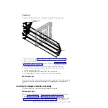
Bezel
1.
Use a flat-blade screwdriver to carefully pull the bezel from the compute node.
2.
Lift the bezel from the compute node.
What to do next
If you are instructed to return the bezel, follow all packaging instructions, and use
any packaging materials for shipping that are supplied to you.
Installing the bezel
Use this information to install the bezel.
Before you begin
Before you install the bezel, read “Safety” on page v and “Installation guidelines”
on page 487.
Chapter 7. Installing, removing, and replacing compute node components
495
Summary of Contents for Flex System x440 Compute Node
Page 1: ...IBM Flex System x440 Compute Node Types 7917 and 2584 Installation and Service Guide ...
Page 2: ......
Page 3: ...IBM Flex System x440 Compute Node Types 7917 and 2584 Installation and Service Guide ...
Page 34: ...22 IBM Flex System x440 Compute Node Types 7917 and 2584 Installation and Service Guide ...
Page 50: ...38 IBM Flex System x440 Compute Node Types 7917 and 2584 Installation and Service Guide ...
Page 68: ...56 IBM Flex System x440 Compute Node Types 7917 and 2584 Installation and Service Guide ...
Page 498: ...486 IBM Flex System x440 Compute Node Types 7917 and 2584 Installation and Service Guide ...
Page 570: ...558 IBM Flex System x440 Compute Node Types 7917 and 2584 Installation and Service Guide ...
Page 578: ...566 IBM Flex System x440 Compute Node Types 7917 and 2584 Installation and Service Guide ...
Page 583: ......
Page 584: ... Part Number 81Y1144 Printed in USA 1P P N 81Y1144 ...