background image

Note: When you connect SAS cables between enclosures, review and follow the guidelines to ensure that

your configuration is valid. Do not begin connecting the cables until you read “SAS cabling guidelines” on

page 63.

Procedure
To install the cables, complete the following steps.

SAS cabling guidelines

When you connect SAS cables between expansion enclosures, you must follow guidelines to ensure that

your configuration is valid.

Orienting the connector
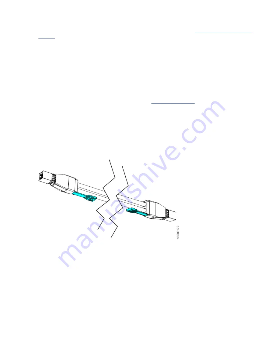
When you insert SAS cables, make sure the connector (Figure 62 on page 63) is oriented correctly.
• The orientation of the connector must match the orientation of the port before you push the connector

into the port. The cable connector and socket are keyed, and it is important that you have proper

alignment of the keys when the cable is inserted.

• Insert the connector gently until it clicks into place. If you feel resistance, the connector is probably

oriented the wrong way. Do not force it.

• When inserted correctly, the connector can be removed only by pulling the tab.
• When both ends of a SAS cable are inserted correctly, the green link LEDs next to the connected SAS

ports are lit.

Figure 62. SAS cable connectors

Guidelines
Be aware of the following guidelines when you attach the cables to the SAS ports.

Connecting SAS cables
Be aware of the following guidelines when you attach the cables to the SAS ports in 2U expansion

enclosures.
• No more than 10 expansion enclosures can be chained to SAS port 1 of a node canister. The expansion

enclosures in this chain must be installed below the control enclosure.

• For systems:

– No more than 10 expansion enclosures can be chained to SAS port 2 of a node canister. The

expansion enclosures in this chain must be installed above the control enclosure.

Chapter 4. Installing the system hardware  63

Summary of Contents for FlashSystem 5000 Series

Page 1: ...IBM FlashSystem 5000 Quick Installation Guide FlashSystem 5010 and FlashSystem 5030 and expansion enclosures IBM...

Page 2: ...vii The information in the IBM Environmental Notices and User Guide provided on a DVD This edition applies to version 8 release 3 modification 1 and to all subsequent modifications until otherwise ind...

Page 3: ...Identify the hardware components 15 Direct current power supply units 15 Verify environmental requirements 19 Review enclosure location guidelines 19 Chapter 4 Installing the system hardware 21 NEBS c...

Page 4: ...ser name and password for system initialization 71 Initializing the system by using the technician port 71 Configuring a system to be NEBS compliant 73 Adding an expansion enclosure to an existing sys...

Page 5: ...ncluding all Amendments under the Low Voltage Directive UL CSA North America bi national harmonized and marked per accredited NRTL agency listings and other such derivative certifications according to...

Page 6: ...vi IBM FlashSystem 5000 FlashSystem 5000 Quick Installation Guide...

Page 7: ...arch for FlashSystem 5000 c Click the documentation link Safety notices and labels Review the safety notices and safety information labels before you use this product To view a PDF file you need Adobe...

Page 8: ...the potential of causing death or serious personal injury D002 CAUTION A caution notice indicates the presence of a hazard that has the potential of causing moderate or minor personal injury C001 2 A...

Page 9: ...abilizer brake function before each use Do not over force moving or rolling the LIFT TOOL with stabilizer brake engaged Do not raise lower or slide platform load shelf unless stabilizer brake pedal ja...

Page 10: ...ay cause serious injury C048 part 2 of 2 CAUTION Removing components from the upper positions in the rack cabinet improves rack stability during a relocation Follow these general guidelines whenever y...

Page 11: ...ing an electrical storm The product might be equipped with multiple power cords To remove all hazardous voltages disconnect all power cords Connect all power cords to a properly wired and grounded ele...

Page 12: ...points marked with R010 Special caution and safety notices This information describes special safety notices that apply to the system These notices are in addition to the standard safety notices that...

Page 13: ...c bag touch it to an unpainted metal part of the system unit for at least 2 seconds This action removes static electricity from the package and from your body Remove the device from its package and in...

Page 14: ...guages The IBM Systems Environmental Notices information includes statements on limitations product information product recycling and disposal battery information flat panel display refrigeration and...

Page 15: ...ection is available at the following website Knowledge Center FlashSystem 5000 library IBM websites for help services and information Table 1 on page xv lists websites where you can find help services...

Page 16: ...sources available from IBM to assist you Information IBM maintains pages on the web where you can get information about IBM products and fee services product implementation and usage assistance break...

Page 17: ...questions about how to use and configure the machine sign up for the IBM Support Line offering to get a professional answer The maintenance that is supplied with the system provides support when there...

Page 18: ...xviii IBM FlashSystem 5000 FlashSystem 5000 Quick Installation Guide...

Page 19: ...logy For more information about the IBM Spectrum Storage portfolio see the following website http www ibm com systems storage spectrum The software provides these functions for the host systems that a...

Page 20: ...wo 12 Gbps SAS port per canister for expansion enclosure attachment 2072 3H4 Up to 24 SFF 2 5 inch drives The system also provides the following functions Large scalable cache Copy Services IBM FlashC...

Page 21: ...nodes canisters operate as a single system System management and error reporting are provided through an Ethernet interface to one of the nodes in the system which is called the configuration node The...

Page 22: ...tachment The optional 4 port 10 Gbps Ethernet host interface adapter can also be installed Not supported iSCSI 25 Gbps Ethernet Yes using an optional 2 port 25 Gbps host interface adapter Not supporte...

Page 23: ...hazardous voltage on the metal parts of the system or the devices that attach to the system It is the responsibility of the customer to ensure that the outlet is correctly wired and grounded to preve...

Page 24: ...rrent Maximum power output Caloric value BTU hr FlashSystem 5000 control enclosures AC 800 W Single phase AC 100 V to 127 V or 200 V to 240 V Frequency 50 60 Hz 100 V to 127 V 9 A 200 V to 240 V 4 5 A...

Page 25: ...er consumption examples per 5U expansion enclosure Model and type Configuration Total power consumption Caloric value BTU hr 2072 92G 2072 F92 1 enclosure with 92 10 TB nearline SAS drives 848 W 2072...

Page 26: ...trol and expansion enclosures Ensure that the rack has enough available space to support each type of enclosure Table 12 Enclosure physical characteristics Enclosure type Model Height Width Depth Maxi...

Page 27: ...ting a 5U 92 drive expansion enclosure The procedure describes what to do for the following situations When you are powering off a 92F 92G or an A9F 5U expansion enclosure because you intend to transp...

Page 28: ...The noise emission level that is stated is the declared upper limit sound power level in decibels for a random sample of enclosures All measurements are made in accordance with ISO 7779 and reported i...

Page 29: ...installed the noise levels from other equipment the room ambient temperature and employees location in relation to the equipment Further compliance with such government regulations also depends upon a...

Page 30: ...Table 18 Supported rack depth Rack Supported depth Standard 19 inch 69 0 cm to 75 0 cm 12 IBM FlashSystem 5000 FlashSystem 5000 Quick Installation Guide...

Page 31: ...at you are supplying are available for installation Be familiar with the following information See Caution notices for the system on page viii and Danger notices for the system on page xi for a summar...

Page 32: ...vices 3 Attach the signal cables to the connectors 4 Attach the power cords to the outlets 5 Turn on the devices Sharp edges corners and joints might be present in and around the system Use care when...

Page 33: ...connect power to this unit only with the IBM provided power cord Do not use the IBM provided power cord for any other product Do not open or service any power supply assembly Do not connect or discon...

Page 34: ...ds This equipment must be installed by trained service personnel in a restricted access location as defined by the NEC and IEC 60950 1 First Edition The Standard for Safety of Information Technology E...

Page 35: ...obstruct the airflow and ensure that all enclosure components or fillers are installed while the system is operational DC power supply LED indicators Each power supply unit has four LED indicators Ta...

Page 36: ...eaker documentation for details Follow the instructions that are given there for connecting the circuit breaker to the power distribution unit and for connecting the DC power cable to the circuit brea...

Page 37: ...ling a system you must verify that adequate space in a suitable rack is available You must also ensure that the requirements for power and environmental conditions are met This guide assumes that you...

Page 38: ...20 IBM FlashSystem 5000 FlashSystem 5000 Quick Installation Guide...

Page 39: ...pport rails and enclosures Upright mounting rails must not be painted oxidized or otherwise insulated from the enclosure flanges and mounting rails If paint oxidization or other insulation is present...

Page 40: ...her looped end of the spring onto the other stud on the inside of the rail Figure 6 Installing the rail spring 3 Working at the front of the rack cabinet identify the two standard rack units 2U of spa...

Page 41: ...provided separately Use the pins that are appropriate for the mounting holes in your rack see Table 23 on page 23 Table 23 Selecting bracket pins for your rack Mounting holes Bracket pins Round unthr...

Page 42: ...pins into the holes in the rack flanges 8 Close the rear hinge bracket to secure the rail to the rack cabinet flange See Figure 9 on page 24 Figure 9 Closing the hinge brackets 9 On the front of the r...

Page 43: ...at least two people To lift a control enclosure with drives installed requires at least three people Load the rack from the bottom up to ensure rack stability Empty the rack from the top down Procedu...

Page 44: ...th the chassis Installing an 5U expansion enclosure Before you start the installation process review the procedures ensure you follow them in the order they are presented 1 Familiarize yourself with t...

Page 45: ...ays completely lower the lift tool load plate and properly secure the load on the lift tool before moving or using the lift tool to lift or move an object D010 DANGER Multiple power cords The product...

Page 46: ...e given to the connection of the equipment to the supply circuit so that overloading of the circuits does not compromise the supply wiring or overcurrent protection To provide the correct power connec...

Page 47: ...let and bolt the rack cabinet to the pallet R002 DANGER Racks with a total weight of 227 kg 500 lb Use Only Professional Movers R003 DANGER Do not transport the rack via fork truck unless it is proper...

Page 48: ...function before each use Do not over force moving or rolling the LIFT TOOL with stabilizer brake engaged Do not raise lower or slide platform load shelf unless stabilizer brake pedal jack is fully eng...

Page 49: ...s injury C048 part 2 of 2 CAUTION If the System slide rails are installed above EIA location 29U the ServerLIFT tool or other qualified lift tool must be used as a safety precaution for servicing Posi...

Page 50: ...unit PSU 3 335 7 352 2 6 670 14 705 Secondary expansion module 0 826 1 821 2 1 652 3 642 Fan module 0 890 1 962 4 3 560 7 848 Expansion canister 1 588 3 501 2 3 176 7 002 Cable management arm lower a...

Page 51: ...d disk drive 0 876 1 931 92 80 592 177 675 As you install or replace FRUs the overall weight of the expansion enclosure increases For example Table 27 on page 33 shows the weight progression as differ...

Page 52: ...initially shipped Enclosure Secondary expansion modules PSUs Expansion canisters Fan modules Fan interface board Display assembly Cover Fascia 1U and 4U Drives 61 5 135 4 Enclosure Secondary expansio...

Page 53: ...y trained persons a lifting device or both to safely lift this part or unit C011 CAUTION To avoid personal injury before lifting this unit remove all appropriate subassemblies per instructions to redu...

Page 54: ...sion enclosure 3 Cut the corners of the shipping box and fold them down to uncover the sides and faces of the expansion enclosure as shown in Figure 13 on page 36 Figure 13 Packaging materials 1 Enclo...

Page 55: ...ing a drive on page 44 14 Replace the top cover as described in Installing or replacing the top cover on page 46 15 Lower the mechanical lift so that you can remove the remaining foam blocks away from...

Page 56: ...expansion enclosure as part of the initial installation process Figure 16 Front fascia of the 5U expansion enclosure Components on the rear of the enclosure Figure 17 on page 38 shows the components o...

Page 57: ...39 shows each CMA assembly is attached to the rear end of the support rails Figure 19 CMA assemblies Removing the top cover To complete some service tasks you might need to remove the top cover from a...

Page 58: ...he support rails before you can install a 5U expansion enclosure in a rack Procedure 1 Locate the hardware that is used to install the rails including the M4xL6 and M5xL13 screws Set the hardware whic...

Page 59: ...taching the inner rail section 4 Use four M4 screws to attach the inner rail to the side of the enclosure Figure 24 on page 41 shows the screw locations Figure 24 Screw locations to attach the inner r...

Page 60: ...e 47 Installing or replacing the fascia During the initial installation process or after you perform service you can install the fascia components on the front of a 5U expansion enclosure About this t...

Page 61: ...ure 2 Replace the four screws to reattach the 4U fascia Secure the screws from the back of the flange and into the rear of the fascia Each side of the 4U fascia contains two screws Attach the bottom 1...

Page 62: ...ing data or access to data the procedures also manage the system s use of the drive About this task The 5U expansion enclosure supports 92 drives Figure 30 on page 44 shows an example of a drive assem...

Page 63: ...15 in row B Figure 32 Correct drive installation In Figure 33 on page 45 the drives are not installed correctly Slot 1 A1 does not contain a drive In addition drives are installed in row B even thoug...

Page 64: ...ng the top cover on page 46 13 Slide the expansion enclosure back into the rack as described in Installing or replacing a 5U expansion enclosure in a rack on page 47 Installing or replacing the top co...

Page 65: ...a 5U expansion enclosure in a rack Use the following procedure to place a 5U expansion enclosure in a rack during the installation process To complete some service tasks you might also need to slide t...

Page 66: ...rails in the extended position 1 in Figure 39 on page 48 Figure 39 Replacing the 5U enclosure in the rack 2 Ensure that the ball bearing retainer clicks into place inside the front of the left and rig...

Page 67: ...sts of an upper arm and a lower arm assembly as Figure 40 on page 49 shows Figure 40 Upper and lower cable management arms As Figure 41 on page 49 shows the support rail connectors of each CMA assembl...

Page 68: ...the support rail 4 Attach the support rail connector on the upper CMA assembly 5 to the connector base on the right support rail 6 as shown in Figure 45 on page 50 Figure 45 Attach the support rail c...

Page 69: ...ar of the system to retain the cables and prevent them from sagging Allow slack in all of the cables to avoid tension in the cables as the CMA moves 9 Reconnect the power cords and other cables as nee...

Page 70: ...inserted you cannot disconnect the cable without pulling on the blue tag Connecting to a system node 7 Connect the SAS cable to the SAS port with blue tab above the connector that is facing towards th...

Page 71: ...ly by pulling the tab Be aware of the following guidelines when you attach the cables to the SAS ports No cable can be connected between a port on a left canister and a port on a right canister of the...

Page 72: ...s The maximum SAS chain weight that can be attached to a node SAS port is 10 5U expansion enclosures have a chain weight of 2 5 2U expansion enclosures have a chain weight of 1 Example Table 28 on pag...

Page 73: ...he 5U expansion enclosure 1 Display panel LEDs 2 Rack retention thumb screws 3 Power supply unit LEDs 4 Power supply units PSUs 5 PSU fascia 1U 6 Front fascia 4U Each PSU has a power supply connector...

Page 74: ...f the enclosure 3 Verify that the expansion enclosure and its components are operating as expected On the back of the expansion enclosure all four fans and the expansion canister indicators 3 and 8 in...

Page 75: ...damage to the drives and makes the lighter enclosure easier to move When you power off an expansion enclosure the drives in that enclosure are no longer available to the control enclosure The SAS chai...

Page 76: ...ontrolled by the system Use the management GUI or service interface to identify an enclosure Off The expansion enclosure is operating normally Enclosure fault Amber On The expansion enclosure is comin...

Page 77: ...ve has an online indicator 2 and fault indicator 3 Figure 58 LEDs on a drive assembly Table 31 on page 59 describes the meaning of the LEDs on each drive Table 31 LED indicators on drives Function Col...

Page 78: ...shows the rear view of a 2072 92G 2072 F92 expansion enclosure LEDs on the rear of the enclosure provide information about each fan module each expansion canister and SAS links Figure 60 LEDs on the b...

Page 79: ...wer 4 and 6 SAS link fault Amber Off No faults are detected All four phys have a link connection On Several error conditions are possible Only 1 2 or 3 phys are connected but not all 4 The phys are no...

Page 80: ...closure supports two secondary expansion modules CAUTION Use caution when you are removing or replacing a secondary expansion module from an enclosure with FRU part number 01LJ112 Avoid contact with t...

Page 81: ...ed Insert the connector gently until it clicks into place If you feel resistance the connector is probably oriented the wrong way Do not force it When inserted correctly the connector can be removed o...

Page 82: ...ction differ across each system model Procedure To install the Ethernet cables complete the following steps 1 If you have a FlashSystem 5010 system complete the following steps a Identify the location...

Page 83: ...on page 65 the technician port is identified by the green cable T Note Never use the technician port to provide an Ethernet connection to the system Do not connect the Ethernet technician port to a ne...

Page 84: ...rrect pair of Ethernet cables for the Ethernet ports labeled 3 in the left canister and the right canister 2 Connect the appropriate cable to each port 3 For each additional pair of Ethernet ports in...

Page 85: ...lling the tab Procedure To install the cables complete the following steps 1 Connect the required number of SAS cables See the Planning section of the IBM Knowledge Center for instructions on determin...

Page 86: ...ecure the cable under the retainer and extend the power cable to the right side of the enclosure Figure 67 Routing the power cables through the cable retainer To remove the power cable push the cable...

Page 87: ...ease ESR 68 4 Microsoft Internet Explorer IE 11 and Microsoft Edge 44 Google Chrome 79 0 Note The minimum viewpoint for browser window for the management GUI is 1024 x 768 Scaling browser view to less...

Page 88: ...ngs c In the Privacy section click Content settings d In the JavaScript section select Allow all sites to run JavaScript e Click OK f Refresh your browser 2 Enable cookies in your web browser For Micr...

Page 89: ...ble JavaScript setting d Select Disable or replace context menus e Click OK to close the Advanced window f Click OK to close the Options window g Refresh your browser User name and password for system...

Page 90: ...e the following steps 1 Access the command line by using the superuser credentials 2 Issue the CLI command mkcluster clusterip x x x x mask m m m m gw g g g g name name to create the system Procedure...

Page 91: ...rsonal computer and the technician port What to do next The system can now be reached by opening a supported web browser and pointing it to http management_IP_address Configuring a system to be NEBS c...

Page 92: ...tically displays on the System Overview page If this action does not appear review the installation instructions to ensure the new enclosure is cabled correctly You can also add a new enclosure by sel...

Page 93: ...osures are in the system you must set up a quorum disk or application outside of the system If the two control enclosures lose communication with each other the quorum disk prevents both I O groups fr...

Page 94: ...76 IBM FlashSystem 5000 FlashSystem 5000 Quick Installation Guide...

Page 95: ...standard devices ports and connectors The system online documentation and its related publications are accessibility enabled The accessibility features of the online documentation are described in Ke...

Page 96: ...78 IBM FlashSystem 5000 FlashSystem 5000 Quick Installation Guide...

Page 97: ...endix B Where to find the Statement of Limited Warranty The Statement of Limited Warranty is available in both hardcopy format and in the FlashSystem 5000 IBM Knowledge Center Copyright IBM Corp 2020...

Page 98: ...80 IBM FlashSystem 5000 FlashSystem 5000 Quick Installation Guide...

Page 99: ...Japan Ltd 19 21 Nihonbashi Hakozakicho Chuo ku Tokyo 103 8510 Japan INTERNATIONAL BUSINESS MACHINES CORPORATION PROVIDES THIS PUBLICATION AS IS WITHOUT WARRANTY OF ANY KIND EITHER EXPRESS OR IMPLIED...

Page 100: ...e names and addresses used by an actual business enterprise is entirely coincidental COPYRIGHT LICENSE This information contains sample application programs in source language which illustrate program...

Page 101: ...terference Germany Notice Deutschsprachiger EU Hinweis Hinweis f r Ger te der Klasse A EU Richtlinie zur Elektromagnetischen Vertr glichkeit Dieses Produkt entspricht den Schutzanforderungen der EU Ri...

Page 102: ...y Tel 49 800 225 5426 e mail Halloibm de ibm com Generelle Informationen Das Ger t erf llt die Schutzanforderungen nach EN 55024 und EN 55032 Klasse A Japan Electronics and Information Technology Indu...

Page 103: ...Japan Voluntary Control Council for Interference VCCI Notice Korea Notice People s Republic of China Notice Russia Notice Taiwan Notice Notices 85...

Page 104: ...interference at his own expense Properly shielded and grounded cables and connectors must be used in order to meet FCC emission limits IBM is not responsible for any radio or television interference c...

Page 105: ......

Page 106: ...IBM...

Reviews: