background image


Chapter 2.  Installing Options

 13

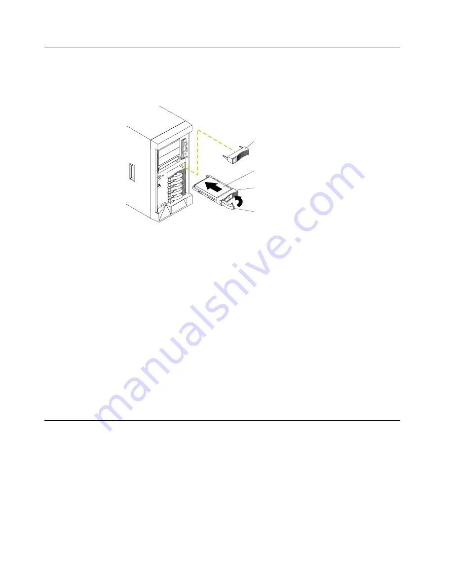
Installing a hot-swap drive

Install

ing hot

-swap dr

ives

The hot-swap drive bay supports hot-swap drives only. Refer to the following 
illustration to install a hot-swap drive.

Note:

The illustrations in this document might differ slightly from your hardware.

To install a drive in a hot-swap drive bay: 

Attention: 

To maintain proper system cooling, do not operate the server for more than two 
minutes without either a drive or a filler panel installed for each bay.

When you handle static-sensitive devices, take precautions to avoid damage from 
static electricity. For details on handling the devices, review “Handling static-
sensitive devices” on page 3.

1.

Remove the filler panel from one of the empty hot-swap bays. 

2.

Ensure the tray handle is in the open position.

3.

Gently push the drive and tray assembly into the bay until the drive touches the 
backplane.

4.

Push the tray handle down into the closed position until it locks.

5.

If you have other options to install, install them now.

6.

If you removed the server cover, reinstall it.

7.

Continue with “Cabling the server” on page 19.

Installing a microprocessor

Install

ing a mi

croproc

essor

Your server comes with one microprocessor installed on the system board. If you 
install an additional microprocessor, your server can operate as a symmetric 
multiprocessing (SMP) server. With SMP, certain operating systems and application 
programs can distribute the processing load between the microprocessors. This 
enhances performance for database and point-of-sale applications, integrated 
manufacturing solutions, and other applications. 

Attention: 

To avoid damage and ensure proper server operation when you install a 

new or additional microprocessor, use microprocessors that have the same cache 
size and type, and the same clock speed. Microprocessor internal and external clock 
frequencies must be identical. See the ServerProven list at 
http://www.ibm.com/pc/compat for a list of microprocessors for use with your server.

Filler panel

Hard disk drive

Drive tray

Drive tray handle
(in open position)

Summary of Contents for eServer 232 xSeries

Page 1: ...e server and options Start the server Install options Drives Microprocessors Adapters Memory Did the server start correctly Yes No Use ServerGuide to setup and configure hardware Did configuration com...

Page 2: ...ing information provided with your server to determine the cause of the problem and the action to take Flash the latest levels of BIOS service processor diagnostics and RAID code You can download this...

Page 3: ...IBM IBM xSeries 232 Installation Guide SC24 P287 20...

Page 4: ...nformation in Appendix A Product warranties and notices on page 39 First Edition June 2001 Copyright International Business Machines Corporation 2001 All rights reserved US Government Users Restricted...

Page 5: ...off the server 21 Controls and indicators 23 Operator information panel 25 Chapter 4 Configuring your server 27 Starting the utility programs 28 Using the Configuration Setup Utility program 28 Starti...

Page 6: ...C Statement 49 Industry Canada Class A emission compliance statement 49 Australia and New Zealand Class A statement 49 United Kingdom telecommunications safety requirement 49 European Union EMC Direct...

Page 7: ...uin asennat t m n tuotteen lue turvaohjeet kohdasta Safety Information Avant d installer ce produit lisez les consignes de s curit Vor der Installation dieses Produkts die Sicherheitshinweise lesen Pr...

Page 8: ...vi IBM xSeries 232 Installation Guide Antes de instalar este producto lea la informaci n de seguridad L s s kerhetsinformationen innan du installerar den h r produkten...

Page 9: ...y equipment when there is evidence of fire water or structural damage Disconnect the attached power cords telecommunications systems networks and modems before you open the device covers unless instru...

Page 10: ...e than 100 C 212 F Repair or disassemble Dispose of the battery as required by local ordinances or regulations Statement 3 CAUTION When laser products such as CD ROMs DVD drives fiber optic devices or...

Page 11: ...ION The power control button on the device and the power switch on the power supply do not turn off the electrical current supplied to the device The device also might have more than one power cord To...

Page 12: ...pply or any part that has the following label attached Hazardous voltage current and energy levels are present inside any component that has this label attached There are no serviceable parts inside t...

Page 13: ...w ibm com eserver xseries For a rack model refer to the Rack Installation Instructions provided with your server for complete installation and removal instructions The server serial number is located...

Page 14: ...eo S3 video controller Compatible with SVGA and VGA 8 MB video memory Size rack model 5U Height 217 mm 8 5 in Depth 688 mm 27 1 in Width 440 mm 17 3 in Weight approximately 35 4 Kg 78 lb when fully co...

Page 15: ...before the description of a potentially lethal or extremely hazardous procedure step or situation Handling static sensitive devices Attention Static electricity can damage electronic devices and your...

Page 16: ...igured to support this function For complete information about installing or removing a hot swap component see the detailed procedures in this chapter The blue color on components and labels indicates...

Page 17: ...ienced user in mind If you need more detailed installation information for options such as tape drives or the 3 pack hard disk drive expansion kit refer to the User s Reference on the IBM xSeries Docu...

Page 18: ...To remove the left side cover of the tower model 1 Turn off the server and all attached devices and disconnect all external cables and power cords 2 Slide the cover release lever on the front of the...

Page 19: ...the server and all attached devices and disconnect all external cables and power cords 2 Move the cover release lever down while sliding the top cover toward the rear of the server approximately 25 mm...

Page 20: ...e switch or jumper settings on your adapter follow the instructions that come with the adapter You can install full length adapters in all expansion slots If using SCSI channel B some full length adap...

Page 21: ...rver Select Start Options from the Configuration Setup Utility program main menu Installing an adapter Refer to the following illustration to install an adapter Note The illustrations in this document...

Page 22: ...on Route cables so that the flow of air from the fans is not blocked In addition route any cables plugged into the PCI card under adjacent cards so they are not pinched between the top of the card and...

Page 23: ...g or removing DIMMs changes the configuration information in the server Therefore after installing or removing a DIMM you must save the new configuration information in the Configuration Setup Utility...

Page 24: ...re in the closed position If a gap exists between the DIMM and the retaining clips the DIMM has not been properly installed In this case open the retaining clips and remove the DIMM then reinsert the...

Page 25: ...position until it locks 5 If you have other options to install install them now 6 If you removed the server cover reinstall it 7 Continue with Cabling the server on page 19 Installing a microprocesso...

Page 26: ...ctor Note After you install the microprocessor store the terminator card in the static protective package for future use 5 Install the microprocessor 6 Install the voltage regulator module VRM include...

Page 27: ...e system board J46 Make sure the cable is not in a position to interfere with the fan sink operation 12 If you have other options to install install them now 13 Install the cover 14 Continue with Cabl...

Page 28: ...D PS1 on the system board diagnostics panel refers to this power supply See the User s Reference on the xSeries Documentation CD for the location of the PS 1 LED Power supply bay 2 Your server comes w...

Page 29: ...p to three power supplies which enables redundancy and will make the power supplies hot swappable After you install a power supply verify that the power supply status indicators ac power light and dc...

Page 30: ...ord for the added power supply into the power cord connector 5 Route the power cord through the cable restraint bracket 6 Plug the power cord into a properly grounded electrical outlet 7 Verify that t...

Page 31: ...might differ slightly from your hardware Additionally for rack models be sure to route the cables through the cable management assembly on the rack see page 20 Note The system management Serial C por...

Page 32: ...20 IBM xSeries 232 Installation Guide Routing cables through the cable management assembly Note The illustrations in this document might differ slightly from your hardware Cable straps...

Page 33: ...e is enabled in the Configuration Setup utility program the wake up feature will turn on the server at the set time If ac power is present the system is off and the Wake on LAN feature is enabled the...

Page 34: ...cause an immediate shutdown of the server and to force the power off You can use this feature if the operating system stops functioning If the system was turned on by the wake up feature or Wake on L...

Page 35: ...your server See Operator information panel on page 25 for more information Tower model Rack model Hard disk drive activity light green Hard disk drive status light amber Reset button Power control bu...

Page 36: ...s light flashes slowly one flash per second the drive is being rebuilt When the light flashes rapidly three flashes per second the controller is identifying the drive Hard disk drive activity light Ea...

Page 37: ...log contains information about certain conditions in your server that might affect performance For example the light will be on if your server has multiple power supplies and does not have redundant p...

Page 38: ...26 IBM xSeries 232 Installation Guide...

Page 39: ...de that comes with your server You can use this program to change network startup boot protocols and startup order to select operating system wake up support and to set menu wait times For information...

Page 40: ...at appear on the screen Using the SCSISelect utility program some models SCSISelect is a built in menu driven configuration utility program that you can use to View the default SCSI IDs Locate and cor...

Page 41: ...tructions needed to start the PXE Boot Agent Utility and descriptions of the menu choices available To start the PXE Boot Agent Utility program 1 Turn on the server 2 When the Initializing Intel R Boo...

Page 42: ...ct your language b Select your keyboard layout and country c View the Overview to learn about ServerGuide features d View the README file to review installation tips about your NOS and adapter e Start...

Page 43: ...ubleshooting charts These charts list problem symptoms along with suggested steps to correct the problems See the Troubleshooting chart on page 35 for more information Error log The POST error log con...

Page 44: ...ponent your keyboard might be defective or a key on the keyboard might be stuck Ensure that Nothing is resting on the keyboard and pressing a key No key is stuck The keyboard cable is connected correc...

Page 45: ...board controller Ensure that the keyboard cable is connected and nothing is resting on the keyboard keys 11xx Serial port error Verify that the serial cable is connected correctly 1162 Serial port con...

Page 46: ...NOS Ensure that there are no duplicate SCSI IDs or IRQ assignments Ensure that the hard disk drive is connected properly The operating system installation program continuously loops Free up more space...

Page 47: ...for service Diskette drive in use light stays on or the system bypasses the diskette drive General problems Call for service Problems such as broken cover locks or indicator lights not working Interm...

Page 48: ...lugged into the server and a working electrical outlet 2 The monitor cables are connected properly 3 The monitor is turned on and the Brightness and Contrast controls are adjusted correctly If the ite...

Page 49: ...the end of the SCSI cable is terminated correctly 3 Any external SCSI option is turned on You must turn on an external SCSI option before turning on the server If the problem remains call for service...

Page 50: ...u have just installed an adapter or memory you might have a memory address conflict 2 The software is designed to operate on your server 3 Other software works on your server 4 The software that you a...

Page 51: ...anty affects any statutory rights of consumers that cannot be waived or limited by contract If you have any questions contact IBM or your reseller The IBM Warranty for Machines IBM warrants that each...

Page 52: ...conformance with their Specifications IBM or your reseller will inform you of the available types of service for a Machine based on its country of installation At its discretion IBM or your reseller w...

Page 53: ...ncluding fundamental breach negligence misrepresentation or other contract or tort claim except for any liability that cannot be waived or limited by applicable laws IBM is liable for no more than 1 d...

Page 54: ...e legislation Limitation of Liability The following is added to this Section Where IBM is in breach of a condition or warranty implied by the Trade Practices Act 1974 or other similar legislation IBM...

Page 55: ...ountry in which you acquired the Machine in the first sentence laws of Hong Kong Special Administrative Region INDIA Limitation of Liability The following replaces items 1 and 2 of this Section 1 liab...

Page 56: ...and France Germany Greece Iceland Ireland Italy Latvia Lithuania Luxembourg Netherlands Norway Portugal Spain Sweden Switzerland or United Kingdom you may obtain warranty service for that Machine in a...

Page 57: ...APPLY TO THE COUNTRY SPECIFIED AUSTRIA AND GERMANY The IBM Warranty for Machines The following replaces the first sentence of the first paragraph of this Section The warranty for an IBM Machine cover...

Page 58: ...d your sole remedy whether in contract or in tort in respect of any default shall be limited to damages ITALY Limitation of Liability The following replaces the second sentence in the first paragraph...

Page 59: ...he user s responsibility to evaluate and verify the operation of any non IBM product program or service IBM may have patents or pending patent applications covering subject matter described in this do...

Page 60: ...o determine the capabilities of their products and update them if needed This IBM hardware product cannot prevent errors that might occur if software upgrades or peripheral devices you use or exchange...

Page 61: ...of this equipment in a residential area is likely to cause harmful interference in which case the user will be required to correct the interference at his own expense Properly shielded and grounded c...

Page 62: ...gainst interference with licensed communication equipment Attention This is a Class A product In a domestic environment this product may cause radio interference in which case the user may be required...

Page 63: ...Czech Republic Egypt Finland France French Guiana Germany Greece Guinea Hungary Iceland Indonesia Iran Ivory Coast Jordan Lebanon Luxembourg Malagasy Mali Martinique Mauritania Mauritius Monaco Moroc...

Page 64: ...52 IBM xSeries 232 Installation Guide...

Page 65: ...ocumentation CD 1 drive 13 installing 13 E electrical vii electrical input 2 electronic emission Class A notice 49 emission requirements electronic emission Class A notice 49 environment air temperatu...

Page 66: ...azardous voltage 17 laser viii lifting ix SCSISelect Utility 27 SCSISelect utility program starting 28 ServeRAID programs 27 ServeRaid See adapter ServerGuide CDs 27 30 ServerGuide CDs 27 shutting dow...

Page 67: ......

Page 68: ...IBM Part Number 24P2872 Printed in the United States of America 24P2872...

Reviews: