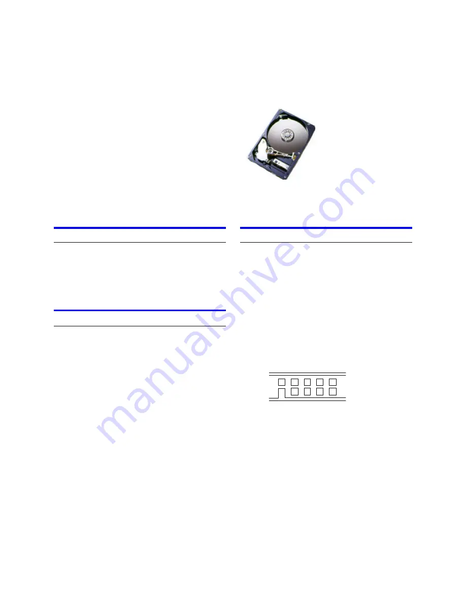
IBM storage products
Page 1
IBM Technology Group Support Center version 1.0
Ibm
Quick installation guide
Deskstar 60GXP
Ultra ATA/100
Models: IC35L010AVER07
IC35L020AVER07
IC35L030AVER07
IC35L040AVER07
IC35L060AVER07
System requirements for Ultra ATA/100
If you do not have the components listed below, your
drive will function but at speeds lower than 100 MB/s.
Ÿ
40 pin, 80 conductor cable
Ÿ
A controller card or motherboard chipset with Ultra
ATA/100 capability
Ÿ
Ultra ATA/100 compatible BIOS or driver
Handling precautions
Ÿ
Set the drive down gently to prevent damage from
impact or vibration.
Ÿ
Do not open the ESD bag containing the drive until
needed.
Ÿ
Handle the drive carefully by the edges. Do not
touch the exposed printed circuit board or any
electronic components.
Ÿ
Do not press on the top or bottom of the drive.
Ÿ
Do not cover the drive breather hole.
Ÿ
Before handling the hard disk drive, discharge any
static electricity from you and your clothing. With
one hand touch an unpainted metal surface on
your computer chassis, then touch the ESD bag
with the other hand. Remain in contact with the
chassis and the bag for a minimum of two seconds.
Quick installation procedure
Note: Back up all data before installing drive!
1. Turn off your computer system.
2. Remove cover as instructed by your computer
system manual.
3. Discharge static electricity per handling pre-
cautions.
4. Unplug your computer.
5. Note mounting position of existing drive(s) and
cable(s). If replacing a drive or cable, remove it.
6. Remove drive from ESD bag.
7. Record model, part, and serial number for future
reference.
8. Refer to the diagram below to set the required
jumpers.
I
A
G
E
C
H
F
D
B
•
If the drive will be the only drive on a cable or
the Master drive on a two-drive cable, leave the
jumpers as set at A-B and G-H for 16 head
logical architecture. The jumpers are factory-set
to Master-16 heads.
•
If the drive will be the Slave drive on a two-
drive cable, set the jumpers at A-B and C-D for
16 logical head architecture.
9. Attach the IDE cable
.
•
If you have a 40-pin 40-conductor cable,
attach the system connector of the
cable to the
IDE port on the
motherboard or controller card.
The pin 1 side of an IDE cable is marked with a
stripe. The connectors are keyed to insert one way
only.
•
If you have a 40-pin 80-conductor cable,
attach the drive to the appropriate color-coded


