


3.
Remove the KVM module from the rear of the system (see “Removing the
KVM module” on page 54).
4.
Remove the LAN module from the rear of the system (see “Removing the
LAN module” on page 55).
5.
Remove the I/O switch that is above the upper flex circuit assembly that you
are removing.
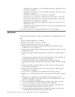
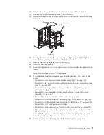
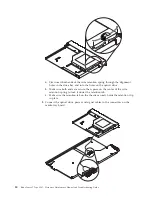
6.
Using a screwdriver, fully loosen the two captive fasteners on the old upper
flex circuit assembly.
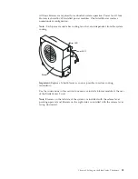
Upper flex circuit assembly
Captive fasteners
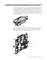
7.
Carefully remove the old upper flex circuit assembly by placing your fingers
under the lower edge of the assembly and pulling the unit out of the chassis.
8.
Remove the new upper flex circuit assembly from the packaging.
9.
Align the assembly so that the stamped position identifier "Top" is facing you.
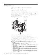
10.
Position the front end of the new upper flex circuit assembly into the
assembly bay in the chassis, making sure the leading edge rests on the lower
shelf of the bay.
CAUTION:
Be careful not to damage the EMI gaskets located on the vertical sides of
the upper flex circuit assembly bay.
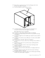
11.
Carefully push the assembly all the way into the bay.
12.
Using a screwdriver, tighten the two captive fasteners on the new upper flex
circuit assembly.
Note:
Torque the screws to 8 inch-pounds.
13.
Reinstall the I/O switch that you removed.
14.
If you have no other replacement procedures to perform at the rear of the
system, reinstall the LAN module (see “Installing the LAN module” on page
55) and the KVM module (see “Installing the KVM module” on page 54).
15.
Reconnect the power to the system (see “Starting the BladeCenter T unit” on
page 16).
16.
Start the system (see “Starting the BladeCenter T unit” on page 16).
Chapter 5. Service replaceable units
65
Summary of Contents for BladeCenter T
Page 1: ...BladeCenter T Type 8267 Hardware Maintenance Manual and Troubleshooting Guide ...
Page 2: ......
Page 3: ...BladeCenter T Type 8267 Hardware Maintenance Manual and Troubleshooting Guide ...
Page 16: ...xiv BladeCenter T Type 8267 Hardware Maintenance Manual and Troubleshooting Guide ...
Page 20: ...xviii BladeCenter T Type 8267 Hardware Maintenance Manual and Troubleshooting Guide ...
Page 52: ...32 BladeCenter T Type 8267 Hardware Maintenance Manual and Troubleshooting Guide ...
Page 102: ...82 BladeCenter T Type 8267 Hardware Maintenance Manual and Troubleshooting Guide ...
Page 126: ...106 BladeCenter T Type 8267 Hardware Maintenance Manual and Troubleshooting Guide ...
Page 138: ...118 BladeCenter T Type 8267 Hardware Maintenance Manual and Troubleshooting Guide ...
Page 139: ......
Page 140: ... Part Number 94Y7061 Printed in USA 1P P N 94Y7061 ...