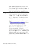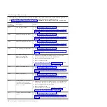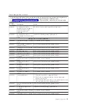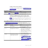
Remove the blade server from the BladeCenter unit, open the cover to see any
error LEDs that were turned on during error processing, and use Figure 3 to
identify the failing component.
PCI-X expansion card
error LED (P1-C10)
Power LED
(always on when plugged in)
DIMM 5 error LED
(P1-C5)
Battery error
LED (P1-E1)
DIMM 6 error LED
(P1-C6)
DIMM 7 error LED
(P1-C7)
DIMM 8 error LED
(P1-C8)
PCIe high-speed
expansion card
error LED (P1-C11)
Management
card error LED
(P1-C9)
DIMM 4 error LED
(P1-C4)
DIMM 3 error LED
(P1-C3)
DIMM 2 error LED
(P1-C2)
DIMM 1 error LED
(P1-C1)
System board
error LED (P1)
Front SAS drive
error LED (P1-D1)
Figure 3. System-board LEDs
10
JS12 Type 7998: Problem Determination and Service Guide
Summary of Contents for BladeCenter JS12
Page 1: ...BladeCenter JS12 Type 7998 Problem Determination and Service Guide...
Page 2: ......
Page 3: ...BladeCenter JS12 Type 7998 Problem Determination and Service Guide...
Page 14: ...xii JS12 Type 7998 Problem Determination and Service Guide...
Page 248: ...234 JS12 Type 7998 Problem Determination and Service Guide...
Page 252: ...238 JS12 Type 7998 Problem Determination and Service Guide...
Page 290: ...276 JS12 Type 7998 Problem Determination and Service Guide...
Page 298: ...284 JS12 Type 7998 Problem Determination and Service Guide...
Page 302: ...288 JS12 Type 7998 Problem Determination and Service Guide...
Page 312: ...298 JS12 Type 7998 Problem Determination and Service Guide...
Page 317: ......
Page 318: ...Part Number 60Y1568 Printed in USA 1P P N 60Y1568...


