support, and manages the remote support session as it progresses. The IBM
service representative connects to the back server by using a Secure Shell (SSH)
client or an HTTPS connection with any browser.
Requirement:
To perform remote support through the Remote Support Center,
your storage system must be able to initiate an outbound SSH connection to IBM.
If the system does not have direct access to the Internet (for example, due to a
firewall), you can use the IBM Remote Support Proxy to facilitate the connection to
IBM. For more information, see the IBM XIV
®
Remote Support Proxy User Guide
(GA32-0795).
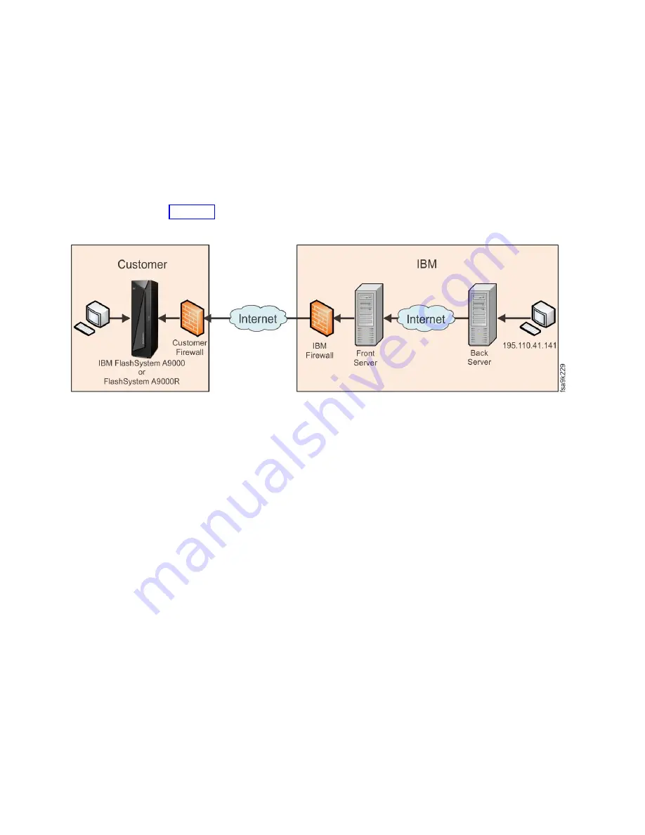
Figure 33 illustrates the remote support components.
The IBM Remote Support Center uses the Secure Shell (SSH) protocol for
transporting data. The encryption used by SSH provides confidentiality and
integrity of the transferred data even over insecure mediums.
To conduct a remote support session, the IBM service representative must explicitly
connect to the IBM Remote Support Center back server. The following secure
remote connection process occurs when a support session is opened:
1.
The customer initiates an Internet SSH connection to the IBM Remote Support
Center.
2.
The IBM Remote Support Center identifies the storage system and marks it as
connected.
3.
The IBM service representative connects to the IBM Remote Support Center
using SSH.
4.
The IBM Remote Support Center authenticates the IBM service representative.
5.
The IBM service representative is shown a list of currently connected storage
systems that correspond with the defined permissions, or the IBM service
representative manually enters the serial number to view the system.
6.
The IBM service representative chooses the storage system to support. Only
permitted systems are displayed, and all activity is logged.
7.
The fully recorded support session commences.
8.
The IBM service representative terminates the support session.
9.
The system disconnects from the IBM Remote Support Center.
While a support session is in progress, the storage system displays the system
status on the IBM Hyper-Scale Manager user interface (UI). You can view the
Figure 33. Remote support components
80
IBM FlashSystem A9000R Models 9835-415 and 9837-415 Deployment Guide
Summary of Contents for 9835-415
Page 1: ...IBM FlashSystem A9000R Models 9835 415 and 9837 415 Deployment Guide GC27 8565 03 IBM ...
Page 5: ...Index 99 Contents v ...
Page 6: ...vi IBM FlashSystem A9000R Models 9835 415 and 9837 415 Deployment Guide ...
Page 8: ...viii IBM FlashSystem A9000R Models 9835 415 and 9837 415 Deployment Guide ...
Page 10: ...x IBM FlashSystem A9000R Models 9835 415 and 9837 415 Deployment Guide ...
Page 22: ...xxii IBM FlashSystem A9000R Models 9835 415 and 9837 415 Deployment Guide ...
Page 26: ...4 IBM FlashSystem A9000R Models 9835 415 and 9837 415 Deployment Guide ...
Page 30: ...8 IBM FlashSystem A9000R Models 9835 415 and 9837 415 Deployment Guide ...
Page 84: ...62 IBM FlashSystem A9000R Models 9835 415 and 9837 415 Deployment Guide ...
Page 100: ...78 IBM FlashSystem A9000R Models 9835 415 and 9837 415 Deployment Guide ...
Page 110: ...88 IBM FlashSystem A9000R Models 9835 415 and 9837 415 Deployment Guide ...
Page 112: ...90 IBM FlashSystem A9000R Models 9835 415 and 9837 415 Deployment Guide ...
Page 120: ...98 IBM FlashSystem A9000R Models 9835 415 and 9837 415 Deployment Guide ...
Page 124: ...102 IBM FlashSystem A9000R Models 9835 415 and 9837 415 Deployment Guide ...
Page 125: ......
Page 126: ...IBM Printed in USA GC27 8565 03 ...


