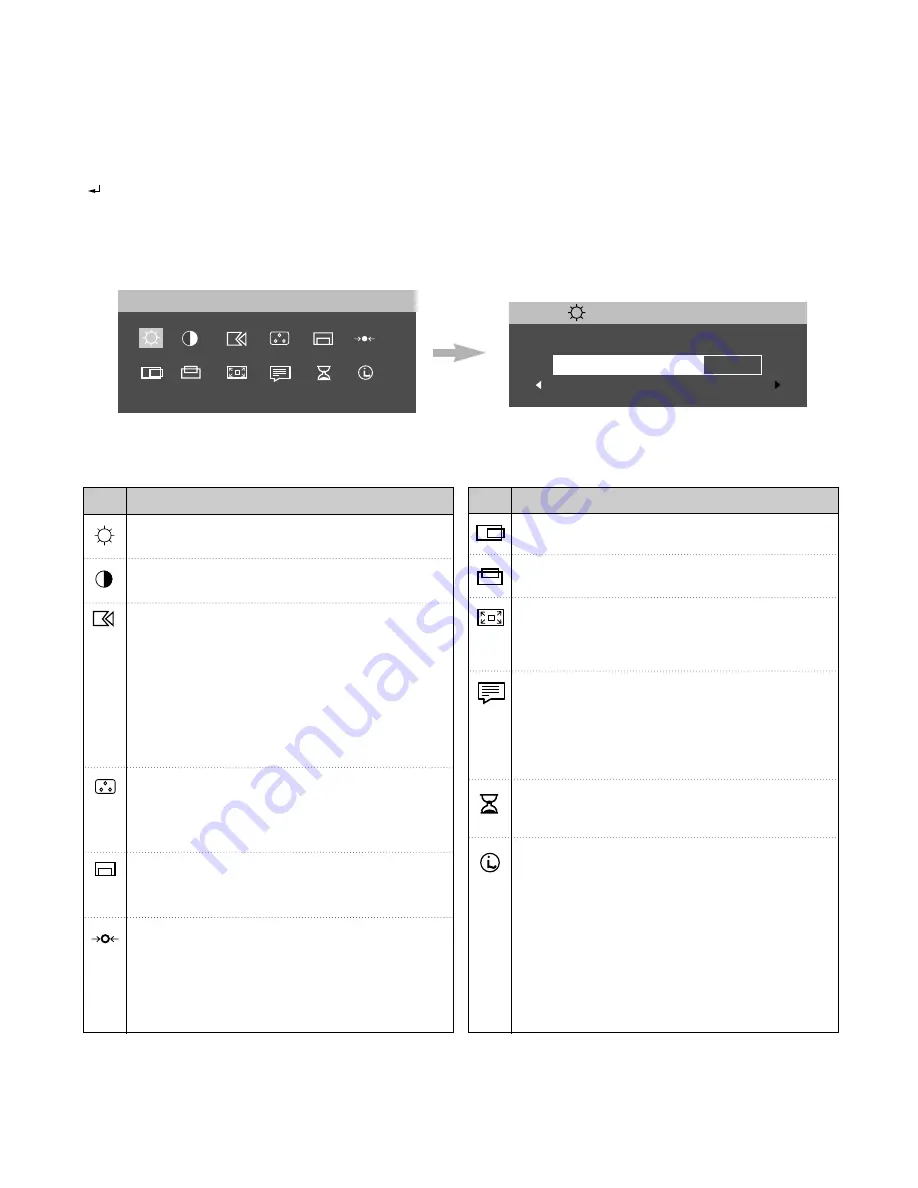
On-Screen-Display (OSD) Control
The settings adjustable with the user controls are viewed through the On -Screen Display (OSD). Press the enter button
[ ] to display the main OSD menu.
Initial appearance of OSD
- 6 -
M A I N M E N U
B R I G H T N E S S
B R I G H T N E S S
7 5
Main Manu;
Sub Manu;
Image Set-Up: The IMAGE SET-UP function
is used to adjust the level of noise in the video
signal which causes horizontal lines or areas
on the screen where the image appears to be
unstable and jitters or shimmers. This can be
done automatically or manually.
If manual is selected, the user will go to the
manual adjustment screen.
Color: Select the Color Mode you find most
comfortable and then fine tune the colors using
the User Color Mode menu, if necessary.
Brightness:
To adjust the screen brightness level.
Contrast: To adjust the image contrast level.
Icon
Description
Listed below are icons, icon names.
OSD Position: Changes the position of the
OSD on the screen.
Reset: Reset should return all available
functions (apart from language which should not
change unless adjusted via the LANGUAGE
menu) fo their factory presets.
Icon
Description
H-Position: Moves the screen left and right.
V-Position: Moves the screen left and right.
Image Size: This function displays the image in
its original size or enlarged size so as to fit in
the full screen of the LCD panel.
Language: The language chosen affects only
the language of the OSD.
Select one of the five language to use for the
OSD. It has no effect on any software running
on the computer.
OSD Time: To select OSD display duration
time. (5 - 60 seconds)
Information: The model name, serial number,
year of manuracture and current display mode
should be included in the Information screen.
To inform users of the current mode the
monitor is using, and also shows the preset
and user modes stored in the monitor. The
current display mode be shown at the base
of the preset mode and user mode displays.
Use the left and rigth buttons to see the preset
modes and user modes screens.
Summary of Contents for 9493-AG1
Page 7: ...WIRING DIAGRAM 7 CN1 CN2 P1 J5 CN3 J2 J3 J1 J4 J10 ...
Page 20: ... 20 1 3 2 4 6 7 8 9 10 11 13 14 12 5 EXPLODED VIEW ...
Page 34: ...SCHEMATIC DIAGRAM 34 1 AD9884 PRE AMP PLL ADC ...
Page 35: ... 35 2 VIDEO PROCESS ...
Page 36: ... 36 3 OUTPUT CONNECTOR ...
Page 37: ... 37 4 MEMORY ...
Page 38: ... 38 5 MICOM ...
Page 39: ... 39 6 POWER GEN ...
Page 40: ... 40 7 CONNECTOR JACKS ...


