background image

Universal


Serial


Bus


connectors


There


are


seven


USB


2.0


connectors


in


the


computer,


two


on


the


front,


four


on


the


rear,


and


one


internal


USB


connector.


Use


the


USB


connectors


to


connect


optional


telephony


and


multimedia


devices.


USB


2.0


technology


transfers


data


at


up


to


480


Mbps


(megabits


per


second)


with


a


maximum


of


127


external


devices,


and


a


maximum


signal


distance


of


5


meters


(16


ft)


per


segment


(if


the


device


that


is


attached


to


the


computer


is


a


USB


2.0


device).


If


multiple


USB


devices


are


attached


to


the


computer,


the


USB


hub


must


be


USB


2.0;


otherwise,


all


USB


2.0


devices


will


transfer


data


at


12


Mbps.


Using


Plug


and


Play


technology,


USB


devices


are


configured


automatically.


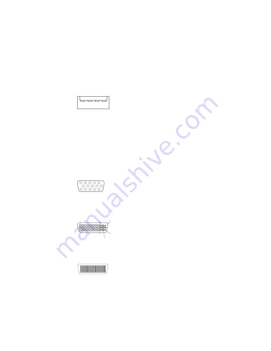
The


following


illustration


shows


a


USB


connector.


1

4


Use


a


4-pin


USB


cable


to


connect


an


external


device


to


a


USB


connector.


Video


connector


The


PCI


Express


x16


adapter


(slot


1)


provides


the


video


connector.


This


connector


is


on


the


rear


of


the


computer.


Use


the


video


connector


to


connect


a


monitor


or


other


display


device.


The


following


illustrations


show


examples


of


different


video


connectors.


Analog


video


connector


1

5

11

15


Digital


(DVI-I)


video


connector


1

C1

C2

C3

C5

C4


Dual


monitor


system-59


(DMS-59)


video


connector


Chapter


4.


Installing


options


63

Summary of Contents for 9228 - IntelliStation Z - Pro

Page 1: ...IBM IntelliStation Z Pro Type 9228 User s Guide...

Page 2: ......

Page 3: ...IBM IntelliStation Z Pro Type 9228 User s Guide...

Page 4: ...d the information in Notices on page 65 First Edition August 2006 Copyright International Business Machines Corporation 2006 All rights reserved US Government Users Restricted Rights Use duplication o...

Page 5: ...or settings 15 Using audio features 15 Using security features 16 Anti intrusion features 16 Component protection 16 Data protection 16 Updating system programs 17 Managing the computer 17 Shutting do...

Page 6: ...ting device connector 61 Ethernet RJ 45 connector 61 IEEE 1394A FireWire connector 62 Keyboard connector 62 Serial connectors 62 Universal Serial Bus connectors 63 Video connector 63 Appendix Notices...

Page 7: ...n tuotteen lue turvaohjeet kohdasta Safety Information Avant d installer ce produit lisez les consignes de s curit Vor der Installation dieses Produkts die Sicherheitshinweise lesen Prima di installar...

Page 8: ...is evidence of fire water or structural damage v Disconnect the attached power cords telecommunications systems networks and modems before you open the device covers unless instructed otherwise in the...

Page 9: ...es or regulations Statement 3 CAUTION When laser products such as CD ROMs DVD drives fiber optic devices or transmitters are installed note the following v Do not remove the covers Removing the covers...

Page 10: ...n the device and the power switch on the power supply do not turn off the electrical current supplied to the device The device also might have more than one power cord To remove all electrical current...

Page 11: ...ld with this product will expose you to lead a chemical known to the State of California to cause cancer and birth defects or other reproductive harm Wash hands after handling ADVERTENCIA El contacto...

Page 12: ...to cross reference an English caution or danger statement with translated versions of the caution or danger statement in the IBM Safety Information document For example if a caution statement begins...

Page 13: ...solve problems yourself and it contains information for service technicians v Safety Information This document is in PDF on the IBM IntelliStation Documentation CD It contains translated caution and d...

Page 14: ...s provide important tips guidance or advice v Important These notices provide information or advice that might help you avoid inconvenient or problem situations v Attention These notices indicate pote...

Page 15: ...ternal v Keyboard connector v Mouse connector v Audio connectors Line out rear Mic front and rear Line in rear Headphone front v Single channel IDE controller Video adapter depending on the model v NV...

Page 16: ...controller on page 25 The controller supports Wake on LAN and Trusted Platform Module TPM technologies v Memory mirroring Some models support memory mirroring Memory mirroring stores data in two pair...

Page 17: ...play DVDs v DVDCreator This software comes on models with DVD write capability You can use this program to create DVDs v Norton Internet Security You can use this program to detect and remove viruses...

Page 18: ...yment and tracking v Remote Deployment Manager Remote Deployment Manager RDM is a graphical server based system deployment program that enables mass unattended installations of operating systems softw...

Page 19: ...menu driven SAS configuration programs some models v Cooling fan with speed sensing capability v Error codes and messages v ECC DDR2 SDRAM with serial presence detect SPD v Hard disk drive partition b...

Page 20: ...8 IBM IntelliStation Z Pro Type 9228 User s Guide...

Page 21: ...tivity LED CD or DVD eject button Headphone connector USB connectors Microphone connector IEEE 1394A FireWire connector Optional diskette drive activity LED Optional diskette eject button 1394 Power o...

Page 22: ...as and external hard disk drives Optional diskette eject button Press this button to release a diskette from the diskette drive Optional diskette drive activity LED When this LED is lit it indicates t...

Page 23: ...ly during startup v Press F1 for Configuration Setup Utility Press F12 for Boot Menu v Press CTRL C to start LSI Logic Configuration Utility some models To start the Product Recovery Program in Red Ha...

Page 24: ...computer You will need the following information to complete the setup program v The documentation that comes with the computer v Network information from the network administrator if the computer is...

Page 25: ...ou can use the recovery repair diskette to access the Product Recovery program For information about using the recovery repair diskette see the Installation Guide on the IBM IntelliStation Documentati...

Page 26: ...r 2 When the message To start the Product Recovery Program Press F11 appears quickly press F11 3 Select System utilities 4 Select Create IBM Enhanced Diagnostics Diskette 5 Follow the instructions on...

Page 27: ...e information that comes with the monitor usually includes resolution and screen refresh rates that the monitor supports If you need additional information contact the manufacturer of the monitor If y...

Page 28: ...bout setting the chassis intrusion alert see Chapter 3 Configuring the computer on page 21 Component protection Each component in the computer has a serial number that you can register with a security...

Page 29: ...otely Instructions for using system program updates are included in a readme file that comes with the downloadable files Managing the computer The computer comes with features that a network administr...

Page 30: ...ith the Wake on LAN feature it can remotely turn on the computer so that installations can be performed while the computer is not being used Shutting down the operating system When you are ready to tu...

Page 31: ...the computer after performing an orderly shutdown of the operating system To turn off the computer from the Microsoft Windows XP operating system click Start Turn Off Computer and click Turn Off To tu...

Page 32: ...20 IBM IntelliStation Z Pro Type 9228 User s Guide...

Page 33: ...e Broadcom NetXtreme Gigabit Ethernet Boot Agent on page 25 v Broadcom NetXtreme Gigabit Ethernet controller configuration To configure the integrated Gigabit Ethernet controller see Configuring the B...

Page 34: ...ly if at least one Preboot eXecution Environment PXE option read only memory ROM starts during POST v System Information Select this choice to view information about the computer When you make changes...

Page 35: ...ns take effect when you start the computer You can set keyboard operating characteristics such as the keyboard speed or specify whether the computer starts with the keyboard number lock on or off You...

Page 36: ...you can type either password at the password prompt that appears as you start the computer However if you want to change the settings in the Configuration Setup Utility program you must type the admin...

Page 37: ...rovides full duplex FDX capability which enables simultaneous transmission and reception of data on the network If the Ethernet port in the computer supports auto negotiation the controller detects th...

Page 38: ...low level format of a SAS hard disk drive v Create an array of SAS hard disk drives with or without a hot spare drive v Set SAS protocol parameters on SAS hard disk drives The integrated SAS controll...

Page 39: ...ft and right use the Left Arrow and Right Arrow keys or the End key Press Alt D 5 To start the low level formatting operation select Format and press Enter Creating a RAID array of SAS hard disk drive...

Page 40: ...28 IBM IntelliStation Z Pro Type 9228 User s Guide...

Page 41: ...e object equally between your feet Use a slow lifting force Never move suddenly or twist when you lift a heavy object To avoid straining the muscles in your back lift by standing or pushing up with yo...

Page 42: ...educe the possibility of damage from electrostatic discharge observe the following precautions v Limit your movement Movement can cause static electricity to build up around you v The use of a groundi...

Page 43: ...tention bracket Rear adapter retention bracket Drive cage EMC shields Filler panels Upper bezel Lower bezel DIMM DIMM airflow guide DIMM fan baffle Cover System board Microprocessor Fan sink Power sup...

Page 44: ...sor 2 Microprocessor 1 Slot 1 PCI Express x16 x16 Slot 3 PCI Express x16 x4 Slot 2 PCI Express x8 x4 Slot 4 PCI X 64 bit 133MHz Slot 5 PCI X 64 bit 133MHz Slot 6 PCI 32 bit 33MHz Diskette drive option...

Page 45: ...12V C power HDD Optical power Microprocessor 2 fan Microprocessor 1 fan Rear fan Front panel audio CD audio in Speaker Debug LPC Intrusion switch Front panel switch LEDs IEEE 1394A FireWire Internal U...

Page 46: ...following illustration shows the external input output connectors on the system board Mouse keyboard Serial USB 3 and 4 USB 5 and 6 IEEE 1394A FireWire Ethernet Audio Front USB 0 and 1 34 IBM Intelli...

Page 47: ...the computer on page 18 then disconnect all power cords and external cables 3 Unlock the side cover 4 Press down on the cover release handle then pull the cover straight up Lift the side cover off th...

Page 48: ...ad the safety information that begins on page v and Installation guidelines on page 29 2 Turn off the computer and all attached devices see Turning off the computer on page 18 then disconnect all powe...

Page 49: ...om the chassis b Rotate the upper bezel to the right side of the computer to disengage the two right side tabs from the chassis Store the bezel for future use For instructions regarding replacing the...

Page 50: ...llation guidelines on page 29 2 Lift the power supply handle and rotate the power supply out of the chassis 3 Press and hold the drive cage release lever then rotate the drive cage completely out of t...

Page 51: ...a double wide adapter in slot 1 it will overlap slot 2 Therefore you will have one less PCI slot available in which you can install an adapter To work around this you can set jumper 10 on the system...

Page 52: ...tions It might be easier to route cables before you install the adapter 5 If an adapter is already installed in the slot remove it using the following procedure and place it on a static protective sur...

Page 53: ...ective package to the adapter slot Align the adapter with the expansion slot guides then press the adapter firmly into the expansion slot Front adapter retention bracket Expansion slot cover Adapter R...

Page 54: ...eplacing the side cover on page 59 Installing internal drives Depending on the computer model one or more of the following drives might be installed in the computer v Hard disk drive v CD RW or DVD CD...

Page 55: ...you install a drive or PCI adapter save the EMC shield and filler panel from the bay or the PCI adapter slot cover in the event that you later remove the drive or adapter v For a complete list of sup...

Page 56: ...panel and EMC shield away from the computer EMC shield Filler panel Drive retainer clip Note If you are installing a drive that contains a laser observe the following safety precaution 44 IBM Intelli...

Page 57: ...ainted metal surface on the computer then remove the drive from the package and place it on a static protective surface 8 Set any jumpers or switches on the drive according to the documentation that c...

Page 58: ...rted only one way 14 Replace the two piece bezel see Replacing the two piece bezel on page 57 15 Replace the side cover see Replacing the side cover on page 59 Installing a simple swap hard disk drive...

Page 59: ...ve assembly into the drive bay until the drive assembly connects to the back panel connector at the rear of the drive bay you should hear a click Note Do not release the loops on the drive assembly un...

Page 60: ...tor is attached to the secondary IDE device Diskette drive optional The narrower signal cable has two connectors One is attached to the diskette drive and the other is attached to the diskette drive c...

Page 61: ...M on the channel v The computer can operate in two major modes mirroring and non mirroring normal The computer can also operate in a single channel mode when one DIMM is installed v The computer suppo...

Page 62: ...rmal mode The computer comes with two 512 MB DIMMs installed in DIMM connectors 1 and 3 The second pair of DIMMs must be installed in DIMM connectors 5 and 7 The third pair of DIMMs must be installed...

Page 63: ...ly out of the chassis until the retaining tab on top of the cage locks into place 7 Locate the DIMM connectors on the system board Determine the connectors into which you will install the DIMMs DIMM 1...

Page 64: ...e microprocessor installed on the system board The computer supports up to two microprocessors Note When installing a microprocessor option lay the computer on its side The following notes describe in...

Page 65: ...onal microprocessor To install the microprocessor and fan sink complete the following steps Orientation indicators Fan sink retention lever Microprocessor 2 Fan sink 2 VRM for microprocessor 2 1 Read...

Page 66: ...et Vacuum tool Microprocessor Socket 12 Install the microprocessor a Squeeze and hold the bladder of the vacuum tool then place the suction cup on the microprocessor and release the bladder Note To ma...

Page 67: ...connector The support bracket hooks into the chassis and the retaining clips snap into the locked position when the VRM is firmly seated in the connector 17 Reconnect any cables that you disconnected...

Page 68: ...d the safety information that begins on page v and Installation guidelines on page 29 2 Turn off the computer and all attached devices 3 Disconnect all external cables and power cords then remove the...

Page 69: ...cover on page 59 Replacing the two piece bezel To replace the two piece bezel complete the following steps 1 Install the upper bezel on the front of the computer chassis Bezel clips a Insert the two r...

Page 70: ...e bezel clips snap into place 2 Install the lower bezel on the front of the computer chassis a Insert the two bottom tabs on the lower bezel into the matching holes in the front of the chassis b Tilt...

Page 71: ...latch to secure the side cover in place 4 Lock the side cover if you unlocked it during removal 5 Reconnect the external cables and power cords to the computer then connect the power cords to electri...

Page 72: ...Four on the rear One internal v Two IEEE 1394A FireWire One on the front One on the rear v One Ethernet v Two audio microphones One on the front One on the rear v Two audio line out One on the front h...

Page 73: ...an external audio device Auxiliary device pointing device connector There is one auxiliary device connector on the rear of the computer Use this connector to connect a mouse or other pointing device...

Page 74: ...3 2 1 6 pin IEEE 1394A FireWire connector rear 1 2 3 4 5 6 Keyboard connector There is one keyboard connector on the rear of the computer Use this connector to connect a PS 2 non USB keyboard The foll...

Page 75: ...er the USB hub must be USB 2 0 otherwise all USB 2 0 devices will transfer data at 12 Mbps Using Plug and Play technology USB devices are configured automatically The following illustration shows a US...

Page 76: ...he video adapter to the computer power supply Otherwise the video adapter will be operating with very limited power resulting in a decrease in performance for some applications Use the PCI Express x16...

Page 77: ...04 1785 U S A INTERNATIONAL BUSINESS MACHINES CORPORATION PROVIDES THIS PUBLICATION AS IS WITHOUT WARRANTY OF ANY KIND EITHER EXPRESS OR IMPLIED INCLUDING BUT NOT LIMITED TO THE IMPLIED WARRANTIES OF...

Page 78: ...Java based trademarks and logos are trademarks of Sun Microsystems Inc in the United States other countries or both Adaptec and HostRAID are trademarks of Adaptec Inc in the United States other countr...

Page 79: ...y differ from its retail version if available and may not include user manuals or all program functionality Product recycling and disposal This unit must be recycled or discarded according to applicab...

Page 80: ...effects of EEE on the environment and human health due to the potential presence of hazardous substances in EEE For proper collection and treatment contact your local IBM representative Battery retur...

Page 81: ...hich the receiver is connected v Consult an IBM authorized dealer or service representative for help Properly shielded and grounded cables and connectors must be used in order to meet FCC emission lim...

Page 82: ...rom a nonrecommended modification of the product including the fitting of non IBM option cards This product has been tested and found to comply with the limits for Class B Information Technology Equip...

Page 83: ...iguration programs continued Broadcom NetXtreme Gigabit Ethernet controller 21 Configuration Setup Utility program 21 general 21 LSI Logic Configuration Utility 21 configuring the computer 21 the Ethe...

Page 84: ...ire connectors 62 IEEE 1394A Firewire enable disable jumper location 33 information related publications 1 installation order memory modules 50 installing adapters 40 drive in bays 2 or 3 43 internal...

Page 85: ...n baffle 38 removing continued side cover 35 replacing DIMM fan baffle 55 the cover 59 retaining clips DIMM 52 rope clip installing for security 56 running the operating system setup program 12 S Safe...

Page 86: ...m programs 17 upper bezel installing 57 using Boot Menu program 24 Configuration Setup Utility program 21 IBM Configuration Setup Utility program 21 LSI Logic Configuration program 26 passwords 23 24...

Page 87: ......

Page 88: ...Part Number 31R2183 Printed in USA 1P P N 31R2183...

Reviews: