


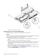
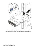


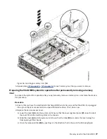
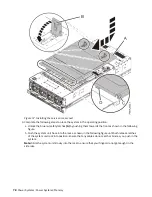

Figure 46. Removing a memory module
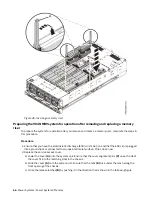
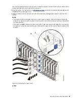
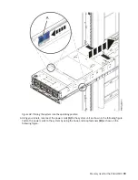
Replacing a memory riser in the 9040-MR9 system
To replace a memory riser in the system, complete the steps in this procedure.
Procedure
1. Ensure that you have the electrostatic discharge (ESD) wrist strap on and that the ESD clip is plugged
into a ground jack or connected to an unpainted metal surface. If not, do so now.
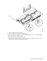
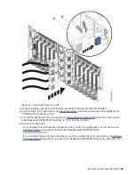
2. Replace the memory modules into the new memory riser:
a) Use the slot information that you recorded to determine the slot location to place the memory
module.
b) Grasp the new memory module along its edges and align it with the slot.
Memory modules are keyed to prevent a memory module from being installed incorrectly. Note the
location of the key tab within the memory module connector before you attempt to install the
memory module.
c) Ensure that the locking tabs of the memory module are open. Slowly press the memory module
straight down, firmly into the slot, until the locking tabs lock into place.
d) Repeat steps “2.a” on page 64 through “2.c” on page 64 for all of the memory modules that reside
on the memory riser you're replacing.
64 Power Systems: Power Systems: Memory
Summary of Contents for 9040-MR9
Page 1: ...Power Systems Memory modules for the 9040 MR9 IBM ...
Page 4: ...iv ...
Page 14: ...xiv Power Systems Power Systems Memory ...
Page 17: ...Figure 1 Removing the power cords L003 or or Memory modules for the 9040 MR9 3 ...
Page 30: ...or or or or 16 Power Systems Power Systems Memory ...
Page 46: ...Figure 23 Removing the power cords L003 or or 32 Power Systems Power Systems Memory ...
Page 59: ...Figure 32 Removing the power cords L003 or or Memory riser for the 9040 MR9 45 ...
Page 70: ...Figure 40 Removing the power cords L003 or or 56 Power Systems Power Systems Memory ...
Page 86: ...or or or or 72 Power Systems Power Systems Memory ...
Page 105: ......
Page 106: ...IBM ...