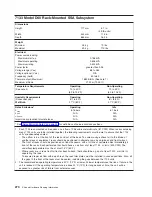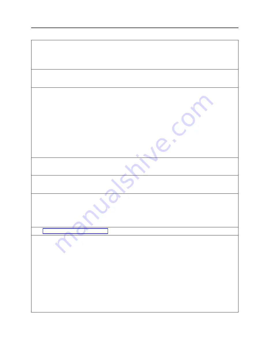
7133 Models 010 and 020 Rack-Mounted SSA Subsystem
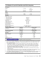
Dimensions
Height
171 mm
6.7 in.
(4 EIA units)
Width
444 mm
17.5 in.
Depth
665 mm
26.2 in.
Weight
Minimum
36 kg
79 lbs.
Maximum
50 kg
110 lbs.
Electrical
Power source loading:
Maximum
start-up
0.657 kVA
Maximum
operating
0.499 kVA
Maximum
idling
0.45 kVA
Power factor
greater than 0.95
Voltage range (V ac)
100 to 240
Voltage optional (V dc)
240 to 375
Frequency (hertz)
50 or 60
DC Power Supply -48 V dc
(Model 020 only)
-40 to -60
Thermal output (Maximum)
2074 Btu/hr (See note 1)
Maximum altitude
2135 m (7000 ft.)
Temperature Requirements
(See note 2)
Operating
10 to 40°C
(50 to 104°F)
Non-Operating
10 to 52°C
(50 to 125°F)
Humidity Requirements
Operating
Non-Operating
(Noncondensing)
8% to 80%
8% to 80%
Wet Bulb
27°C (80°F)
27°C (80°F)
Noise Emissions*
Operating
Idle
L
WAd
6.15 bels
6.1 bels
L
pAm
N/A
N/A
<L
pA
>
m
48 dBA
45 dBA
Impulsive or prominent
discrete tones
No
No
* See “Noise Emission Notes” on page 336 for definitions of noise emissions positions.
1. Each 7133 rack-mounted unit requires an air flow of 2.46 cubic meters/minute (87 CFM). When racks containing
many 7133 units are to be installed together, the following requirements must be met to ensure that the 7133
units are adequately cooled:
v
The airflow is in at the front of the rack and out at the back. To avoid moving exhaust air to the intake of
another piece of equipment, racks should be positioned in alternate rows, back-to-back and front-to-front.
v
The front of racks should be positioned on floor-tile seams, with a full line of perforated tiles immediately in
front of the racks. Each perforated tile should have an air flow of at least 11.34 m
³
/min (400 CFM). The
underfloor temperature must be at most 15°C (60°F).
v
Where racks are in rows front-to-front or back-to-back, there should be a gap of at least 1220 mm (48 in)
separating the rows.
v
To ensure proper air flow within each rack, the rack filler plates must be installed in unused positions. Also, all
the gaps in the front of the racks must be sealed, including the gaps between the 7133 units.
2. The recommended operating temperature is 22°C (72°F) or lower. At lower temperatures, the risk of failure in the
unit is reduced. If the operating temperature is above 22°C (72°F) for long periods of time, the unit will be
exposed to a greater risk of failure from external causes.
Chapter 7. Physical Characteristics of the 7100 Series
269
Summary of Contents for 7012 397
Page 1: ...RS 6000 and Eserver pSeries Site and Hardware Planning Information SA38 0508 20...
Page 2: ......
Page 3: ...RS 6000 and Eserver pSeries Site and Hardware Planning Information SA38 0508 20...
Page 11: ...Appendix Notices 385 Index 387 Contents ix...
Page 12: ...x Site and Hardware Planning Information...
Page 16: ...xiv Site and Hardware Planning Information...
Page 18: ...xvi Site and Hardware Planning Information...
Page 26: ...8 Site and Hardware Planning Information...
Page 238: ...220 Site and Hardware Planning Information...
Page 246: ...228 Site and Hardware Planning Information...
Page 284: ...266 Site and Hardware Planning Information...
Page 296: ...278 Site and Hardware Planning Information...
Page 366: ...348 Site and Hardware Planning Information...
Page 372: ...Async Adapter Cable Planning Chart 354 Site and Hardware Planning Information...
Page 377: ...Standard I O Cable Planning Chart Chapter 12 Cable Planning 359...
Page 380: ...Cable Planning Chart Other Adapters 362 Site and Hardware Planning Information...
Page 384: ...366 Site and Hardware Planning Information...
Page 402: ...384 Site and Hardware Planning Information...
Page 404: ...386 Site and Hardware Planning Information...
Page 413: ......
Page 414: ...Printed in USA SA38 0508 20...
Page 415: ...Spine information RS 6000 and Eserver pSeries Site and Hardware Planning Information...

