Behavior on overload
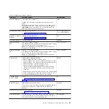
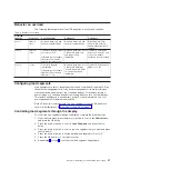
The following table explains how the UPS responds to an overload condition.
Table 9. Behavior on overload
Overload
severity
Load level
On utility power
On Bypass
On battery
Level 1
100% to
101%
Overload alarm only and
support load indefinitely
Overload alarm only and
support load indefinitely
Overload alarm only,
support load until low
battery shutdown level is
reached
Level 2
102% to
110%
Transfer to Bypass after 12
seconds (±1 sec)
If Bypass is not available,
transfer to Fault mode
after 12 seconds (±1 sec)
Overload alarm plus "Level
2 Overload" alarm only
and support load
indefinitely
Transfer to Fault mode
after 12 seconds (±1 sec)
or until low battery
shutdown level is reached
Level 3
> 110%
Transfer to Bypass
immediately
If Bypass is not available,
transfer to Fault mode in
300 ms to 1 sec
Overload alarm plus "Level
2 Overload" alarm plus
"Level 3 Overload" alarm
only and support load
indefinitely
Transfer to Fault mode in
300 ms to 1 sec
Configuring load segments
Load segments are sets of receptacles that can be controlled through the LCD, by
the network management card, or by power-management software, providing an
orderly shutdown and startup of the connected devices. For example, during a
power outage, you can keep key devices running while you turn off other devices.
This feature enables you to save battery power. For more information, see your
power-management software documentation.
Each UPS has two load segments. The load segments for each UPS model are
shown in the illustrations in “Rear view of the UPS” on page 7.
Controlling load segments through the display
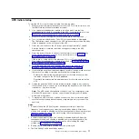
To control the load segments through the display, complete the following steps:
1. From the main menu, press the down (
) button to scroll to the
Control
menu,
and press the OK button.
2. Press the down (
) button to scroll to
Load Segments
, and press the OK
button.
3. Press the down (
) button to scroll to the load segment that you want and press
the OK button.
4. Press the down (
) button to set the desired load segment to On or Off.
5. Press the OK button for 1 second to confirm.
6. Repeat step 3 to step 5 to set the other load segment, if applicable.
Chapter 3. Operating the uninterruptible power supply
27
Summary of Contents for 6000 VA LCD 4U
Page 2: ......
Page 14: ...xii 6000 VA UPS and 6000 VA EBM Installation and Maintenance Guide...
Page 32: ...18 6000 VA UPS and 6000 VA EBM Installation and Maintenance Guide...
Page 60: ...46 6000 VA UPS and 6000 VA EBM Installation and Maintenance Guide...
Page 70: ...56 6000 VA UPS and 6000 VA EBM Installation and Maintenance Guide...
Page 74: ...60 6000 VA UPS and 6000 VA EBM Installation and Maintenance Guide...
Page 82: ...68 6000 VA UPS and 6000 VA EBM Installation and Maintenance Guide...
Page 86: ...72 6000 VA UPS and 6000 VA EBM Installation and Maintenance Guide...
Page 87: ......
Page 88: ...Part Number 81Y1032 Printed in USA 1P P N 81Y1032...

