background image

System-board


internal


connectors


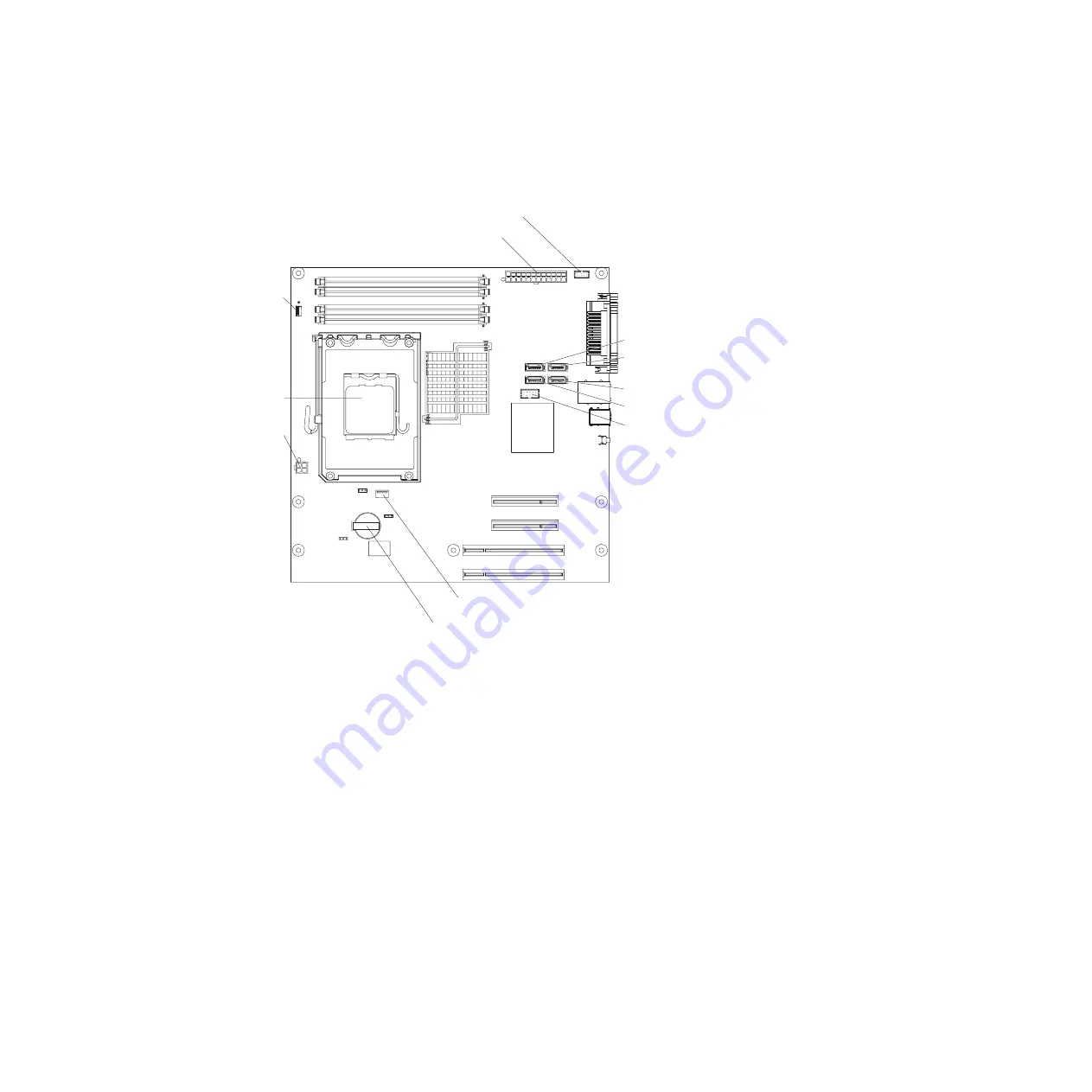
The


following


illustration


shows


the


internal


connectors


on


the


system


board.


Main power (ATX 12V) connector

Front control panel connector

SATA 0

SATA 3

SATA 2

SATA 1

Internal USB (tape drive)

Battery

Microprocessor

Microprocessor
fan

Microprocessor
power

Front
panel USBs


12


System


x3100


Type


4348:


User’s


Guide

Summary of Contents for 4348

Page 1: ...System x3100 Type 4348 User s Guide ...

Page 2: ......

Page 3: ...System x3100 Type 4348 User s Guide ...

Page 4: ...7 and the Warranty and Support Information document on the IBM System x Documentation CD First Edition March 2008 Copyright International Business Machines Corporation 2008 All rights reserved US Government Users Restricted Rights Use duplication or disclosure restricted by GSA ADP Schedule Contract with IBM Corp ...

Page 5: ... side cover 17 Removing the bezel 18 Installing a memory module 19 Installing a drive 22 Installing a DVD drive 23 Installing an optional tape drive 26 Installing a SATA hard disk drive 26 Power and signal cables for internal drives 28 Installing an adapter 29 Cabling an optional SCSI adapter 31 Completing the installation 31 Installing the bezel 32 Installing the side cover 33 Connecting the cabl...

Page 6: ...Gigabit Ethernet Boot Agent program 45 Configuring the Intel Gigabit Ethernet controller 45 Appendix Notices 47 Trademarks 47 Important notes 48 Product recycling and disposal 49 Battery return program 50 Index 53 iv System x3100 Type 4348 User s Guide ...

Page 7: ...talleert eerst de veiligheidsvoorschriften Ennen kuin asennat tämän tuotteen lue turvaohjeet kohdasta Safety Information Avant d installer ce produit lisez les consignes de sécurité Vor der Installation dieses Produkts die Sicherheitshinweise lesen Prima di installare questo prodotto leggere le Informazioni sulla Sicurezza Les sikkerhetsinformasjonen Safety Information før du installerer dette pro...

Page 8: ...ct or disconnect signal cables v Never turn on any equipment when there is evidence of fire water or structural damage v Disconnect the attached power cords telecommunications systems networks and modems before you open the device covers unless instructed otherwise in the installation and configuration procedures v Connect and disconnect cables as described in the following table when installing m...

Page 9: ...ces or regulations Statement 3 CAUTION When laser products such as CD ROMs DVD drives fiber optic devices or transmitters are installed note the following v Do not remove the covers Removing the covers of the laser product could result in exposure to hazardous laser radiation There are no serviceable parts inside the device v Use of controls or adjustments or performance of procedures other than t...

Page 10: ...utton on the device and the power switch on the power supply do not turn off the electrical current supplied to the device The device also might have more than one power cord To remove all electrical current from the device ensure that all power cords are disconnected from the power source 1 2 viii System x3100 Type 4348 User s Guide ...

Page 11: ...earby Statement 13 DANGER Overloading a branch circuit is potentially a fire hazard and a shock hazard under certain conditions To avoid these hazards ensure that your system electrical requirements do not exceed branch circuit protection requirements Refer to the information that is provided with your device for electrical specifications Important Each caution and danger statement in this documen...

Page 12: ... IBM Safety Information document under Statement 1 Be sure to read all caution and danger statements in this documentation before you perform the procedures Read any additional safety information that comes with the server or optional device before you install the device x System x3100 Type 4348 User s Guide ...

Page 13: ...to customize the system hardware to meet your needs today and provide flexible expansion capabilities for the future The server comes with a limited warranty For information about the terms of the warranty and getting service and assistance see the Warranty and Support Information document The server contains technology that helps increase performance reliability and availability For more informat...

Page 14: ...Depending on the server model additional documentation might be included on the IBM System x Documentation CD The System x and xSeries Tools Center is an online information center that contains information about tools for updating managing and deploying firmware device drivers and operating systems The System x and xSeries Tools Center is at http publib boulder ibm com infocenter toolsctr v1r0 ind...

Page 15: ...at might help you avoid inconvenient or problem situations v Attention These notices indicate potential damage to programs devices or data An attention notice is placed just before the instruction or situation in which damage might occur v Caution These statements indicate situations that can be potentially hazardous to you A caution statement is placed just before the description of a potentially...

Page 16: ...RJ 45 Ethernet port v One serial port v One parallel port v Four port Serial ATA II controller v Six Universal Serial Bus USB v2 0 ports two on front and four on rear v One internal USB port for tape drive v ATI ES1000 video Compatible with SVGA and VGA 32 MB DDR2 video memory Diagnostic LEDs v Fans v Memory Acoustical noise emissions v Sound power idling 5 0 bel v Sound power operating 5 3 bel En...

Page 17: ...ernet controller which supports connection to a 10 Mbps 100 Mbps or 1000 Mbps network For more information see Configuring the Intel Gigabit Ethernet controller on page 45 v Large system memory capacity The server supports up to 8 GB of system memory The memory controller supports error correcting code ECC for up to four industry standard 1 8 V 240 pin double data rate 2 DDR2 PC2 5300 or PC2 6400 ...

Page 18: ...ting code ECC double data rate 2 DDR2 synchronous dynamic random access memory SDRAM with serial presence detect SPD v Error logging of POST failures v Integrated Ethernet controller v Memory change messages posted to the error log v Power on self test POST v Read only memory ROM checksums v Redundant Ethernet capabilities requires an optional Ethernet adapter with failover support v Standby volta...

Page 19: ...tors Connect a USB device to these connectors System error LED When this amber LED is lit it indicates that a system error has occurred An LED on the system board might also be lit to help isolate the error Hard disk drive activity LED When this LED is flashing it indicates that the hard disk drive is in use Power control button Press this button to turn the server on and off manually A power cont...

Page 20: ...SB 4 connector USB 3 connector USB 2 connector USB 1 connector Power supply voltage switch Power supply voltage switch 115 115 Power cord connector Connect the power cord to this connector Power supply error LED When this amber LED is lit it indicates that a power supply error has occurred Power supply voltage switch Use this switch to change the system ac power supply input voltage for your geogr...

Page 21: ...owever the server can respond to requests such as a remote request to turn on the server When the power on LED is flashing it indicates that the server is connected to ac power but is not turned on Setting the power supply voltage Before you turn on the server make sure that you do the following 1 Remove the clear tape from the ac power supply voltage switch on the rear of the server 2 Set the pow...

Page 22: ...vice also might have more than one power cord To remove all electrical current from the device ensure that all power cords are disconnected from the power source 1 2 The server can be turned off in any of the following ways v You can turn off the server from the operating system if your operating system supports this feature After an orderly shutdown of the operating system the server will be turn...

Page 23: ...r components The following illustration shows the major components in the server The illustrations in this document might differ slightly from your hardware Filler panels DVD drive Optional diskette drive Bezel Power supply Drive cage DIMM System board Cover Air baffle Front adapter retention bracket Hard disk drive Copyright IBM Corp 2008 11 ...

Page 24: ... internal connectors on the system board Main power ATX 12V connector Front control panel connector SATA 0 SATA 3 SATA 2 SATA 1 Internal USB tape drive Battery Microprocessor Microprocessor fan Microprocessor power Front panel USBs 12 System x3100 Type 4348 User s Guide ...

Page 25: ...ot block jumper JP3 System board external connectors The following illustration shows the external input output connectors on the system board Video connector Parallel connector Serial COM1 connector Ethernet connector USB 1 connector USB 3 connector USB 2 connector USB 4 connector NMI connector Chapter 2 Installing optional devices 13 ...

Page 26: ...4 LED Microprocessor fan LED System board optional device connectors The following illustration shows the system board connectors for user installable options DIMM 1 DIMM 2 DIMM 3 DIMM 4 Slot 1 PCI Express x8 x4 Slot 2 PCI Express x8 Slot 3 PCI 32 bit 33MHz Slot 4 PCI 32 bit 33MHz 14 System x3100 Type 4348 User s Guide ...

Page 27: ...ack lift by standing or by pushing up with your leg muscles v Back up all important data before you make changes to disk drives v Have a small flat blade screwdriver available v Blue on a component indicates touch points where you can grip the component to remove it from or install it in the server open or close a latch and so on v Orange on a component or an orange label on or near a component in...

Page 28: ...rge observe the following precautions v Limit your movement Movement can cause static electricity to build up around you v The use of a grounding system is recommended For example wear an electrostatic discharge wrist strap if one is available v Handle the device carefully holding it by its edges or its frame v Do not touch solder joints pins or exposed circuitry v Do not leave the device where ot...

Page 29: ...move the two thumbscrews from the rear of the server that secure the cover to the chassis Press down slightly on the depressed area slide the cover toward the rear of the chassis lift it off the server and set it aside Thumbscrews To replace the side cover see Installing the side cover on page 33 Attention For proper cooling and airflow replace the cover before you turn on the server Operating the...

Page 30: ...elines on page 15 3 Turn off the server and all attached devices see Turning off the server on page 10 then disconnect all power cords and external cables 4 From inside the server locate the bezel release tab at the bottom of the bezel Press the bezel release tab and then pull the bottom of the bezel away from the server to disengage the top bezel tabs from the server and set the bezel aside Bezel...

Page 31: ...d DIMM specification For a list of supported DIMMs for your server see http www ibm com servers eserver serverproven compat us v The DIMM options that are available for the server are 512 MB 1 GB and 2 GB The server supports a minimum of 512 MB and a maximum of 8 GB of system memory v The amount of usable memory will be reduced depending on the system configuration A certain amount of memory must ...

Page 32: ...lowing steps 1 Locate the DIMM connectors on the system board Determine the connectors into which you will install the DIMMs DIMM 1 LED DIMM 2 LED DIMM 3 LED DIMM 4 LED DIMM 1 DIMM 2 DIMM 3 DIMM 4 20 System x3100 Type 4348 User s Guide ...

Page 33: ...e connector by aligning the edges of the DIMM with the slots at the ends of the DIMM connector Firmly press the DIMM straight down into the connector by applying pressure on both ends of the DIMM simultaneously The retaining clips snap into the locked position when the DIMM is firmly seated in the connector If there is a gap between the DIMM and the retaining clips the DIMM has not been correctly ...

Page 34: ...you install removable media and hard disk drives v Read the documentation that comes with the drive and make sure that you have all the cables and other equipment specified in the documentation that comes with the drive v The server supports a maximum of two hard disk drives four DIMMs and one 5 25 inch device or one hard disk drive four DIMMs and two 5 25 inch devices or two hard disk drives two ...

Page 35: ...xpress adapter save the EMC shield and filler panel from the bay or the PCI or PCI Express adapter slot cover in the event that you later remove the drive or adapter v For a complete list of supported optional devices for the server see http www ibm com support Installing a DVD drive To install a DVD drive in bay 1 or 2 complete the following steps 1 Read the safety information that begins on page...

Page 36: ...he bezel then pry the EMC shield away from the server with a screwdriver Store the filler panel and EMC shield in a safe place Release tab Drive retainer clip EMC shield Note If you are installing a drive that contains a laser observe the following safety precaution 24 System x3100 Type 4348 User s Guide ...

Page 37: ...ce 7 Set any jumpers or switches on the drive according to the documentation that comes with the drive 8 Remove the drive retainer clip on the front of the chassis for the bay in which you want to install the drive see the illustration on page 27 Slide the drive retainer clip to the right to remove it from the chassis then snap the drive retainer clip into the screw holes on the side of the drive ...

Page 38: ...ackage and place it on a static protective surface 7 Slide the tape drive into the drive cage from the front of the server then connect the SATA cable to the tape drive EMC shield 8 Secure the tape drive to the chassis with the supplied screws 9 Connect the tape drive cable to the tape drive connector on the system board If you have other devices to install or remove do so now otherwise go to Comp...

Page 39: ...e drive cage from the server if you find it easier to install and remove hard disk drives by pressing in on the locking latch on the side of the drive cage indicated by a blue dot and lift it out of the server Locking latch Thumbscrew 6 Touch the static protective package that contains the drive to any unpainted metal surface on the server then remove the drive from the package and place it on a s...

Page 40: ...e server come with attached power and signal cables If you replace any drives remember which cable is attached to which drive v When you install a drive make sure that one of the signal cable drive connectors is connected to the drive and that the connector at the other end of the signal cable is connected to the system board v When you route a cable make sure that it does not block the airflow to...

Page 41: ...slot 1 PCI Express slot 2 system board integrated drive electronics IDE or SCSI devices and then PCI slots 3 and 4 v For a list of supported optional devices for the server see http www ibm com servers eserver serverproven compat us To install an adapter complete the following steps 1 Read the safety information that begins on page v and Installation guidelines on page 15 2 Turn off the server and...

Page 42: ...ete installation of an adapter might damage the system board or the adapter Rear adapter retention bracket Front adapter retention bracket Expansion slot cover 8 Reinstall the screw that you removed from the expansion slot earlier to secure the adapter to the chassis 9 Connect required cables to the adapter Route cables so that they do not block the flow of air from the fan If you are installing a...

Page 43: ... SCSI adapter complete the following steps 1 Install the SCSI adapter see Installing an adapter on page 29 2 Connect the SCSI signal cable to the adapter and to one or more of the connectors on the rear of the SCSI devices SCSI cable SCSI adapter SCSI connector 3 Complete the installation of the SCSI adapter see Installing an adapter on page 29 Completing the installation To complete the installat...

Page 44: ...Insert the two alignment tabs at the top of the bezel into the bezel retention slots at the top of the chassis Bezel retention slots Bezel alignment tabs 2 Push the bottom of the bezel toward the server until the bezel snaps into place 32 System x3100 Type 4348 User s Guide ...

Page 45: ... installed and seated correctly and that you have not left loose tools or parts inside the server 2 Align the cover over the server with the rear of the cover slightly hanging off the rear of the server and slide the cover toward the front of the server until it is completely closed Thumbscrews 3 Use the two thumbscrews that you removed earlier to secure the cover to the server chassis Chapter 2 I...

Page 46: ...ion To prevent damage to equipment connect the power cords last The following illustration shows the input output I O connectors on the rear of the server Power cord connector Power supply error LED AC power LED Video connector Parallel connector Serial connector Ethernet Ethernet activity LED Ethernet speed indication LED USB 4 connector USB 3 connector USB 2 connector USB 1 connector Power suppl...

Page 47: ... additional information Some devices have device drivers that you must install See the documentation that comes with each device for information about installing device drivers If the server has an optional RAID adapter and you have installed or removed a hard disk drive see the RAID adapter documentation for information about reconfiguring the disk arrays For information about configuring the int...

Page 48: ...36 System x3100 Type 4348 User s Guide ...

Page 49: ... use it to configure the network as a startable device and you can customize where the network startup option occurs in the startup sequence Enable the Intel Gigabit Ethernet Boot Agent from the Configuration Setup Utility program For information see Enabling the Intel Gigabit Ethernet Boot Agent program on page 45 v Intel Gigabit Ethernet controller configuration For information about configuring...

Page 50: ...tem Information Select this choice to view information about the server When you make changes through other choices in the Configuration Setup Utility program some of those changes are reflected in the system information you cannot change settings directly in the system information Select this choice to view the machine type and model of the server the serial number and the revision level or issue...

Page 51: ... the start options Changes in the start options take effect when you restart the server You can set keyboard operating characteristics such as the keyboard speed and you can specify whether the server starts with the keyboard number lock on or off You can enable the server to run without a diskette drive monitor or keyboard The startup sequence specifies the order in which the server checks device...

Page 52: ...save the changes that you have made in the settings v Restore Settings Select this choice to cancel the changes that you have made in the settings and restore the previous settings v Load Default Settings Select this choice to cancel the changes that you have made in the settings and restore the factory settings v Exit Setup Select this choice to exit from the Configuration Setup Utility program I...

Page 53: ...figuration Setup Utility menu only if an optional IBM Remote Supervisor Adapter II is installed Resetting passwords If you forget the power on password or administrator password you can regain access to the server in any of the following ways v If an administrator password is set type the administrator password at the password prompt Start the Configuration Setup Utility program and reset the powe...

Page 54: ...ng password or create a new password 12 Select Save Settings and press Enter Using the ServerGuide Setup and Installation CD The ServerGuide Setup and Installation CD contains a setup and installation program that is designed for the IBM server The ServerGuide program detects the server model and optional hardware devices that are installed and uses that information during setup to configure the h...

Page 55: ...erating system CD to install the operating system The ServerGuide program performs the following tasks v Sets system date and time v Detects an installed SCSI RAID adapter and runs the SCSI RAID configuration program v Checks the microcode firmware levels of a ServeRAID adapter and determines whether a later level is available from the CD v Detects installed optional hardware devices and provides ...

Page 56: ...de program prompts you to insert your operating system CD and restart the server At this point the installation program for the operating system takes control to complete the installation Installing your operating system without using ServerGuide If you have already configured the server hardware and you are not using the ServerGuide program to install your operating system complete the following ...

Page 57: ...grated on the system board It provides an interface for connecting to a 10 Mbps 100 Mbps or 1 Gbps network and provides full duplex FDX capability which enables simultaneous transmission and reception of data on the network If the Ethernet port in the server supports auto negotiation the controller detects the data transfer rate 10BASE T 100BASE TX or 1000BASE T and duplex mode full duplex or half...

Page 58: ...46 System x3100 Type 4348 User s Guide ...

Page 59: ...CLUDING BUT NOT LIMITED TO THE IMPLIED WARRANTIES OF NON INFRINGEMENT MERCHANTABILITY OR FITNESS FOR A PARTICULAR PURPOSE Some states do not allow disclaimer of express or implied warranties in certain transactions therefore this statement may not apply to you This information could include technical inaccuracies or typographical errors Changes are periodically made to the information herein these...

Page 60: ...ries or both Red Hat the Red Hat Shadow Man logo and all Red Hat based trademarks and logos are trademarks or registered trademarks of Red Hat Inc in the United States and other countries Other company product or service names may be trademarks or service marks of others Important notes Processor speeds indicate the internal clock speed of the microprocessor other factors also affect application p...

Page 61: ...ion on IBM product recycling offerings can be found on IBM s Internet site at http www ibm com ibm environment products index shtml Esta unidad debe reciclarse o desecharse de acuerdo con lo establecido en la normativa nacional o local aplicable IBM recomienda a los propietarios de equipos de tecnología de la información TI que reciclen responsablemente sus equipos cuando éstos ya no les sean útil...

Page 62: ... to minimize any potential effects of EEE on the environment and human health due to the potential presence of hazardous substances in EEE For proper collection and treatment contact your local IBM representative Battery return program This product may contain a sealed lead acid nickel cadmium nickel metal hydride lithium or lithium ion battery Consult your user manual or service manual for specif...

Page 63: ...de vie selon cette norme In accordance with the European Directive 2006 66 EC batteries and accumulators are labeled to indicate that they are to be collected separately and recycled at end of life The label on the battery may also include a chemical symbol for the metal concerned in the battery Pb for lead Hg for mercury and Cd for cadmium Users of batteries and accumulators must not dispose of b...

Page 64: ...52 System x3100 Type 4348 User s Guide ...

Page 65: ... 33 D danger statements 3 data rate Ethernet 45 DIMM connector installing memory 20 locations 20 DIMM retaining clips 21 diskette drive installing 26 drive bay filler panel 24 installation 26 drives installing 22 DVD drive installation 23 DVD ROM drive activity LED 7 eject button 7 installing 22 specifications 4 E eject button DVD ROM 7 electrical input 4 enabling Intel Gigabit Ethernet Utility 45...

Page 66: ...ation 39 40 PCI expansion slots 4 power control button 7 power supply specifications 4 power supply voltage 8 setting 9 power switch 7 power cord connector 8 power on LED 7 processor control 40 R RAS features 5 RAS See also features reliability availability and serviceability 5 related documentation 2 reliability features 5 Remote Supervisor Adapter configuration 37 removable media drives installi...

Page 67: ...ure 4 trademarks 47 U using Boot Menu program 44 IBM Configuration Setup Utility program 37 passwords 39 40 V video 4 video controller 4 voltage for power supply setting 9 W Web site compatible options 15 ServerGuide 43 weight 4 Index 55 ...

Page 68: ...56 System x3100 Type 4348 User s Guide ...

Page 69: ......

Page 70: ... Part Number 44W2351 Printed in USA 1P P N 44W2351 ...

Reviews: