OSR
IBM 4019
Diagnostics Mode
To use service and maintenance aids, you must put the machine in the Diagnostics
Mode.
To enter the Diagnostics Mode:
1.
Turn the printer off.
2.
Press and hold the Print/Check, Paper and Font buttons while you turn on
the printer. Release the buttons when the operator panel lights come on.
3.
The printer runs the Power-On Self Test (POST).
4.
7
is displayed, the Ready light is on. Operator panel button functions in the
Diagnostics Mode:
Start/Stop Page Count view or change
Print/Check Registration Adjustment
Paper Wrap Test
Orientation Diagnostics Print Test Pages
5.
To exit this mode, turn off the printer.
Diagnostics Print Test
The printer runs two printouts of the Diagnostic Print Test. This test runs paper out
of the 200-sheet tray (tray 1) only and formats the printout to system defaults.
To run the Print Test:
1.
Enter the Diagnostics Mode.
2.
Press the Orientation button. The printer will run two diagnostic printouts.
Paper Feed Test
This test allows you to observe the drive gear train and run paper through the
machine with the top cover open.
To perform the Paper Feed Test:
1.
Turn off the printer.
2.
Remove the print cartridge and leave the cover open.
3.
Remove the gear cover.
CAUTION:
The fuser is hot and the gears will run.
4.
Turn on the printer while holding the Print/Check, Paper, and Font buttons.
5.
Continue to hold one of the above buttons to run the motor.
6.
If you want to feed paper, put a sheet in the manual feed slot, while the
motors are running. The motor will not start if paper is over the paper sensors
while the motor is idle. Clear the paper and start the motor again by pressing
and holding any button.
7.
Release all buttons, then install the gear cover and print cartridge.
8.
Close the top cover, then press an operator panel button. The machine will
complete warm-up and go to the Main Menu.
Adjustments
Envelope Restraint Spring
1.
Loosen the mounting screw.
2.
Position the spring so it clears the separator roller by 1.7-2.1 mm (.067-.083
in).
3.
Tighten the mounting screw.
Envelope Feed Magnet
1.
Hold the armature in the closed (coil active) position.
2.
Loosen the mounting screw and rotate the magnet assembly so the armature
clears the clutch gear by 0.4
±
0.2 mm (.016
±
.024 in)
3.
Tighten the screw.
4.
Check the adjustment on both sides of the gear.
Optional Paper Feed Magnet Adjustment
1.
Latch the armature onto the cam gear.
2.
Adjust the magnet as follows:
a.
Plastic armature: so there is 0.81
±
0.1 mm (.032
±
.004 in) between
the armature and the pole piece.
b.
Steel armature: so there is 1.0
±
0.1 mm (.039
±
.004 in) between the
armature and the pole piece.
3.
Tighten the mounting screw.
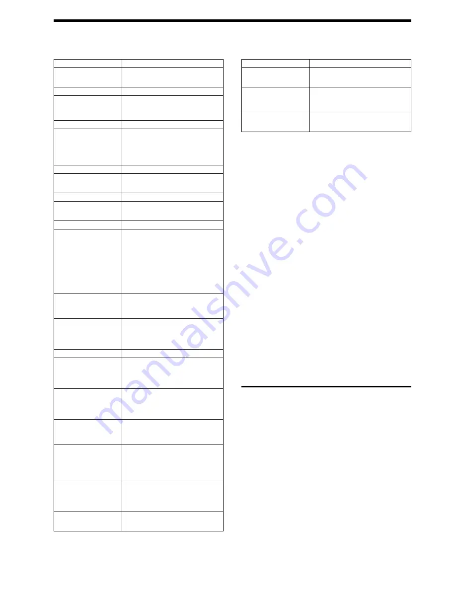
Symptom
Possible Causes
Symptom
Possible Causes
Lights or buttons do not work
correctly
Operator panel
System board
System cable 1.
Spots or marks at regular inter-
vals
Fuser unit
Gears binding or broken
Feed roller 69 mm.
Envelope Feed
Vertical void, streak, or dis-
tortion
Print head contamination
Print head shutter does not open completely
Fuser unit
Transfer corona.
Envelope feeder does not work
correctly
Envelope magnet adjustment
Envelope restraint spring
Worn or broken parts
System board.
Toner light does not work cor-
rectly
Toner sensor
Toner sensor cable
System board defective.
Fuser Unit
Check Code, repeat images,
paper jams, printing smears
Thermistor defective
Fuse blown
Fuser unit defective
Fuser lamp blown
Power cable loose or defective
System board defective.
Print Head
Check Code
Print quality
Lost or skewed print.
Print head cable loose or defective
Print head defective
Mirror motor cable loose or defective.
Cover Interlock
Check Code 1
HVPS
LVPS
System board.
Paper Feed
Check Code 2 or the paper:
Jams
Misfeeds
Feeds continuously
Fails to stack
Has poor registration
Drive motor does not run.
Dirty, damaged, or worn paper feed mech-
anism parts
Dirty, damaged, or worn fuser unit
Dirty, damaged, or worn transfer corona
Failing paper feed magnet
Failing D-roller
Paper condition
System board defective
Paper sensor
Paper sensor cable
Drive motor failing.
Optional paper module mis-
feeds, feeds continuously, jams,
or cannot be selected
Paper drawer
D-roller worn or defective
Drive roller worn or defective
System board defective.
Printout is not registered cor-
rectly.
Drive motor wrong speed
Drive gears loose or worn
Input sensor faulty
Paper feed roller worn
System board defective.
Print Quality
Poor print quality due to back-
ground.
Transfer corona
System board defective
Erase lamps
HVPS
Fuser.
Black printout
Print head
System board defective
Poor contact to the charge corona.
HVPS
System cable loose or defective.
Blurred or skewed print
Gear drive train
Print head
Paper feed slippage
Transfer corona.
Horizontal void, streak, or dis-
tortion
Transfer corona contact intermittent
HVPS contact intermittent
Print head
Paper feed path interference
Bad paper
System board defective.
Light printing or blank printout.
Print head
Transfer corona
System board defective
HVPS
Flex cable.
Spots or marks on the printout
Machine contamination
Fuser unit
Machine environment.
95-05-26
All rights reserved.
LM-2
3


