background image

5.


Touch


the


static-protective


package


that


contains


the


DIMM


to


any


unpainted


metal


surface


on


the


outside


of


the


server.


Then,


remove


the


DIMM


from


the


package.


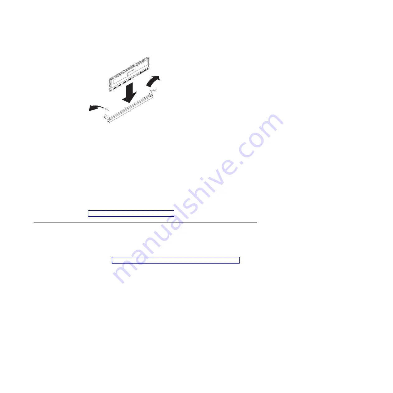
6.


Turn


the


DIMM


so


that


the


DIMM


keys


align


correctly


with


the


slot.


7.


Insert


the


DIMM


into


the


connector


by


aligning


the


edges


of


the


DIMM


with


the


slots


at


the


ends


of


the


DIMM


connector.


8.


Firmly


press


the


DIMM


straight


down


into


the


connector


by


applying


pressure


on


both


ends


of


the


DIMM


simultaneously.


The


retaining


clips


snap


into


the


locked


position


when


the


DIMM


is


firmly


seated


in


the


connector.


Note:


If


there


is


a


gap


between


the


DIMM


and


the


retaining


clips,


the


DIMM


has


not


been


correctly


inserted;


open


the


retaining


clips,


remove


the


DIMM,


and


then


reinsert


it.


If


you


have


other


options


to


install


or


remove,


do


so


now.


Otherwise,


go


to


“Completing


the


installation”


on


page


45.

Installing


a


microprocessor


The


following


notes


describe


the


type


of


microprocessor


that


the


server


supports


and


other


information


that


you


must


consider


when


installing


a


microprocessor:


v


The


server


supports


certain


Intel


Xeon


dual-core


or


quad-core


flip-chip


land


grid


array


771


(FC-LGA


771)


microprocessors,


which


are


designed


for


the


LGA771


socket.


See


http://www.ibm.com/servers/eserver/serverproven/compat/us/


for


a


list


of


supported


microprocessors.


Important:


Dual-core


and


quad-core


microprocessors


are


not


interchangeable


and


cannot


be


used


in


the


same


server.


For


example,


if


the


server


has


a


dual-core


microprocessor,


you


cannot


install


a


quad-core


microprocessor


as


the


second


microprocessor.


Use


the


Configuration/Setup


Utility


program


to


determine


the


type


and


speed


of


the


microprocessor


that


is


currently


installed


in


the


server.


At


the


time


of


this


publication,


the


following


System


x3550


server


models


come


with


quad-core


microprocessors:


7978-A1x


7978-A1Y


7978-C1x


7978-C1Y


7978-CCx


7978-C2x


7978-C3x


7978-CBx


Chapter


2.


Installing


options


39

Summary of Contents for 3550 Type 7978

Page 1: ...IBM System x3550 Type 7978 User s Guide ...

Page 2: ......

Page 3: ...IBM System x3550 Type 7978 User s Guide ...

Page 4: ...age 79 and the Warranty and Support Information document on the IBM System x Documentation CD Fourth Edition September 2008 Copyright International Business Machines Corporation 2006 2008 US Government Users Restricted Rights Use duplication or disclosure restricted by GSA ADP Schedule Contract with IBM Corp ...

Page 5: ...side the server with the power on 24 Handling static sensitive devices 25 Removing the server cover 25 Removing air baffles 26 Installing a hot swap power supply 28 Installing a Y power cable 30 Installing a hard disk drive 30 Installing a hot swap hard disk drive 31 Installing a simple swap hard disk drive 32 Replacing a riser card assembly 33 Installing an adapter 34 Replacing the RAID SAS contr...

Page 6: ...n Utility program 74 Setting up an Remote Supervisor Adapter II SlimLine 75 Requirements 75 Cabling the Remote Supervisor Adapter II SlimLine 75 Installing the Remote Supervisor Adapter II SlimLine firmware 76 Completing the setup 76 Appendix Notices 79 Trademarks 79 Important notes 80 Product recycling and disposal 81 Battery return program 82 Electronic emission notices 84 Federal Communications...

Page 7: ... tuotteen lue turvaohjeet kohdasta Safety Information Avant d installer ce produit lisez les consignes de sécurité Vor der Installation dieses Produkts die Sicherheitshinweise lesen Prima di installare questo prodotto leggere le Informazioni sulla Sicurezza Les sikkerhetsinformasjonen Safety Information før du installerer dette produktet Antes de instalar este produto leia as Informações sobre Seg...

Page 8: ...y Information book For example if a caution statement begins with a number 1 translations for that caution statement appear in the IBM Safety Information book under statement 1 Be sure to read all caution and danger statements in this documentation before performing the instructions Read any additional safety information that comes with the server or optional device before you install the device v...

Page 9: ...equipment when there is evidence of fire water or structural damage v Disconnect the attached power cords telecommunications systems networks and modems before you open the device covers unless instructed otherwise in the installation and configuration procedures v Connect and disconnect cables as described in the following table when installing moving or opening covers on this product or attached...

Page 10: ...g a lithium battery replace it only with the same module type made by the same manufacturer The battery contains lithium and can explode if not properly used handled or disposed of Do not v Throw or immerse into water v Heat to more than 100 C 212 F v Repair or disassemble Dispose of the battery as required by local ordinances or regulations viii IBM System x3550 Type 7978 User s Guide ...

Page 11: ...the device v Use of controls or adjustments or performance of procedures other than those specified herein might result in hazardous radiation exposure DANGER Some laser products contain an embedded Class 3A or Class 3B laser diode Note the following Laser radiation when open Do not stare into the beam do not view directly with optical instruments and avoid direct exposure to the beam Class 1 Lase...

Page 12: ...utton on the device and the power switch on the power supply do not turn off the electrical current supplied to the device The device also might have more than one power cord To remove all electrical current from the device ensure that all power cords are disconnected from the power source 1 2 x IBM System x3550 Type 7978 User s Guide ...

Page 13: ... a power supply or any part that has the following label attached Hazardous voltage current and energy levels are present inside any component that has this label attached There are no serviceable parts inside these components If you suspect a problem with one of these parts contact a service technician Statement 12 CAUTION The following label indicates a hot surface nearby Safety xi ...

Page 14: ...defects or other reproductive harm Wash hands after handling ADVERTENCIA El contacto con el cable de este producto o con cables de accesorios que se venden junto con este producto pueden exponerle al plomo un elemento químico que en el estado de California de los Estados Unidos está considerado como un causante de cancer y de defectos congénitos además de otros riesgos reproductivos Lávese las man...

Page 15: ...ays support 3 5 inch hot swap SAS or 3 5 inch hot swap Serial ATA SATA hard disk drives You can install only 3 5 inch hot swap SAS or hot swap SATA drives in these servers v Servers with two simple swap bays support 3 5 inch simple swap SATA hard disk drives You can install only 3 5 inch simple swap SATA drives in these servers The following illustration shows a System x3550 server with a hot swap...

Page 16: ...s printed document contains instructions for installing the server in a rack v Problem Determination and Service Guide This document is in PDF on the IBM System x Documentation CD It contains information to help you solve problems yourself and it contains information for service technicians v Warranty and Support Information This document is in PDF on the IBM System x Documentation CD It contains ...

Page 17: ... or advice v Important These notices provide information or advice that might help you avoid inconvenient or problem situations v Attention These notices indicate potential damage to programs devices or data An attention notice is placed just before the instruction or situation in which damage could occur v Caution These statements indicate situations that can be potentially hazardous to you A cau...

Page 18: ...llowing information is a summary of the features and specifications of the server Depending on the form factor server some features might not be available or some specifications might not apply 4 IBM System x3550 Type 7978 User s Guide ...

Page 19: ...nd two rear v One Advanced System Management RJ 45 active only when a Remote Supervisor Adapter II SlimLine is installed v One serial port Hard disk controllers v Serial ATA SATA controller with integrated RAID simple swap SATA models v Serial attached SCSI SAS controller with integrated RAID hot swap SAS models Acoustical noise emissions v Sound power idling 6 8 bels maximum v Sound power operati...

Page 20: ...cture technology combines proven innovative IBM designs to make your Intel processor based server powerful scalable and reliable For more information see http www ibm com servers eserver xseries xarchitecture enterprise index html Active Memory The Active Memory feature improves the reliability of memory through memory mirroring and online spare memory Memory mirroring stores data in two pairs of ...

Page 21: ...e see the IBM Director documentation on the IBM Director CD or see www ibm com servers eserver xseries systems_management ibm_director extensions v Redundant connection The addition of an optional network interface card NIC provides failover capability to a redundant Ethernet connection If a problem occurs with the primary Ethernet connection all Ethernet traffic that is associated with the primar...

Page 22: ... v Backup basic input output system BIOS switching under the control of the BMC v Built in monitoring for fan power temperature voltage and power supply redundancy v Cable presence detection on most connectors v Chipkill memory protection v Error codes and messages v Error correcting code ECC L2 cache and system memory v Hot swap hard disk drives some drives v Information and light path diagnostic...

Page 23: ... support IBM Director see the IBM Director Compatibility Document This document is in Portable Document Format PDF at http www ibm com pc support site wss document do lndocid MIGR 61788 It is updated every 6 to 8 weeks v Support for IBM and non IBM servers desktop computers workstations and mobile computers v Support for systems management industry standards v Integration into leading workgroup an...

Page 24: ...inch hard disk drives Video connector USB 4 connector USB 3 connector Rack release latch Rack release latch Operator information panel CD RW DVD drive activity LED Hard disk drive activity LED Hard disk drive status LED CD RW DVD eject button The following illustration shows the controls LEDs and connectors on the front of the server This configuration supports up to two 3 5 inch hot swappable har...

Page 25: ...e error This LED is controlled by the BMC Release latch Press the release latch to the left to slide out the operator information panel and view the light path diagnostics LEDs and buttons See the Problem Determination and Service Guide for more information about the light path diagnostics panel System information LED When this amber LED is lit it indicates that a noncritical event has occurred Ch...

Page 26: ... drive v Hard disk drive activity LED This LED is used on SAS hard disk drives Each hot swap hard disk drive has an activity LED and when this LED is flashing it indicates that the drive is in use Light path diagnostics panel The light path diagnostics panel is on the top of the operator information panel To access the light path diagnostics panel push the release button on the operator panel to t...

Page 27: ...ce Guide on the IBM System x Documentation CD Rear view The following illustration shows the connectors and LEDs on the rear of the server PCI slot 1 PCI slot 2 Video connector Serial connector USB 1 USB 2 Ethernet 1 Ethernet 2 Systems management Ethernet connector Power on LED AC power LED DC power LED System locator LED System error LED Power connector v PCI slot 1 Insert a PCI Express type adap...

Page 28: ...hernet connector Use this connector to connect the server to a network for systems management information control This connector is active only if you have installed a Remote Supervisor Adapter II SlimLine and it is used only by the Remote Supervisor Adapter II SlimLine v Ethernet activity LEDs When these LEDs are lit they indicate that the server is transmitting to or receiving signals from the E...

Page 29: ...em The amount of memory that is reserved for system resources depends on the operating system the configuration of the server and the configured PCI options Turning off the server When you turn off the server and leave it connected to ac power the server can respond to requests from the service processor such as a remote request to turn on the server While the server remains connected to ac power ...

Page 30: ...n orderly shutdown of the operating system the server will turn off automatically v You can press the power control button to start an orderly shutdown of the operating system and turn off the server if your operating system supports this feature v If the operating system stops functioning you can press and hold the power control button for more than 4 seconds to turn off the server v If you insta...

Page 31: ...e cage 3 5 inch SAS hard disk drive Air baffle 3 5 inch SATA hard disk drive 3 5 inch filler panel simple swap 3 5 inch filler panel hot swap 2 5 inch hard disk drive backplane 2 5 inch hard disk drive cage 2 5 inch hard disk drive 2 5 inch filler panel hot swap Power backplane Operator information panel CD RW DVD drive Fans 3 6 Fans 1 2 Power supply filler Power supply System board PCI X riser ca...

Page 32: ... Operator information panel connector USB front panel connector USB3 and USB4 Video front panel connector SAS signal connector J65 some models SATA 1 signal connector port 1 some models SATA 0 signal connector port 0 some models Microprocessor 1 connector Power supply backplane connector 18 IBM System x3550 Type 7978 User s Guide ...

Page 33: ...lustration shows the external input output connectors on the system board Video connector Serial connector USB 1 connector USB 2 connector Ethernet 1 connector Ethernet 2 connector Ethernet connector Systems management Chapter 2 Installing options 19 ...

Page 34: ...nd jumpers The following illustration shows the switches and jumpers on the system board System board switch block SW2 NMI SW1 8 7 6 5 4 3 2 1 ON 1 2 3 Boot block recovery jumper J14 20 IBM System x3550 Type 7978 User s Guide ...

Page 35: ...lt LED BMC status LED PCI slot 1 error LED Fan 6 error LED Fan 2 error LED Fan 1 error LED Fan 5 error LED Fan 4 error LED Fan 3 error LED Power B error LED Power A error LED Power C error LED Power D error LED PCI slot 2 error LED Power on LED Location LED System error LED RAID error LED Microprocessor 2 error LED Microprocessor 1 error LED Light path diagnostics active LED Light path diagnostics...

Page 36: ...to route the cables for optional devices The illustration also shows where the two air baffles are located For some devices you might have to remove the baffles to correctly route the cables Air baffle Air baffle with cable guide 22 IBM System x3550 Type 7978 User s Guide ...

Page 37: ...on will help you work safely v Observe good housekeeping in the area where you are working Place removed covers and other parts in a safe place v If you must start the server while the server cover is removed make sure that no one is near the server and that no tools or other objects have been left inside the server v Do not attempt to lift an object that you think is too heavy for you If you have...

Page 38: ...upply bays has a power supply installed in it v There is adequate space around the server to allow the server cooling system to work properly Leave approximately 50 mm 2 0 in of open space around the front and rear of the server Do not place objects in front of the fans For proper cooling and airflow replace the server cover before turning on the server v You have followed the cabling instructions...

Page 39: ...the outside of the server for at least 2 seconds This drains static electricity from the package and from your body v Remove the device from its package and install it directly into the server without setting down the device If it is necessary to set down the device put it back into its static protective package Do not place the device on the server cover or on a metal surface v Take additional ca...

Page 40: ...oling and airflow replace the server cover before you turn on the server Removing air baffles There are two air baffles inside the server These air baffles direct air to cool components inside the server You might have to remove these baffles to access certain components or connectors on the system board such as DIMMs IDE cables or microprocessors To remove an air baffle complete the following ste...

Page 41: ...from the bulkhead that runs the width of the server b Lift the baffle up making sure that the pins come out of the holes on the system board Attention For proper cooling and airflow replace the air baffle before you turn on the server Operating the server with the air baffle removed might damage server components Chapter 2 Installing options 27 ...

Page 42: ...e server components Installing a hot swap power supply The following notes describe the type of power supply that the server supports and other information that you must consider when installing a power supply v The server comes with one 670 watt hot swap 12 volt output power supply The input voltage is 110 V ac or 220 V ac auto sensing v You can install an optional 670 watt hot swap 12 volt outpu...

Page 43: ...ty information that begins v and Installation guidelines on page 23 2 Remove the protective power supply cover from the back of the server Note The server comes with this protective cover over both power supply openings Tab Release latch Press in on the release tab on the outside of the cover Move the cover off the power supplies by swinging the cover to the left then remove it from the tab on the...

Page 44: ... right of the power cord connector If you have other options to install or remove do so now Otherwise go to Completing the installation on page 45 Installing a Y power cable A Y power cable comes with the power supply option Cable the servers as shown in the illustration to ensure server redundancy Use one Y power cable to provide power to two servers Each Y power cable must be connected to a diff...

Page 45: ...TA drives in these servers v Servers with two simple swap bays support 3 5 inch simple swap SATA hard disk drives You can install only 3 5 inch simple swap SATA drives in these servers v All hot swap drives in the server should have the same throughput speed rating Mixing hard disk drives with different speed ratings will cause all drives to operate at the lower throughput speed v Do not mix SAS a...

Page 46: ...n page 45 Installing a simple swap hard disk drive To install a 3 5 inch SATA simple swap hard disk drive complete the following steps Note If you have only one hard disk drive you must install it in the left bay Filler panel Drive tray assembly SATA hard disk drive back plate 1 Read the safety information that begins on page v and Installation guidelines on page 23 2 Turn off the server and disco...

Page 47: ...dapter support bracket Expansion slot cover Riser card connector 3 Remove the PCI Express riser card assembly from slot 2 on the system board v If an adapter is installed in the riser card assembly disconnect any cables that are connected to the adapter v Grasp the riser card assembly at the rear edge and lift it from the riser card connector v Remove the adapter if one is present from the riser c...

Page 48: ...eral devices and disconnect the power cords and all external cables if necessary then remove the server cover Riser card assembly Adapter support bracket Expansion slot 2 Expansion slot cover Riser card connector PCI adapter 3 Follow the cabling instructions if any come with the adapter Route the adapter cables before you install the adapter 4 Insert the adapter into the riser card assembly aligni...

Page 49: ...page 23 2 Turn off the server and peripheral devices and disconnect the power cords Remove the server cover 3 Remove the ServeRAID 8k l SAS controller from the connector a Open the retaining clip on each end of the connector Attention To avoid breaking the retaining clips or damaging the connectors handle the clips gently b Carefully grasp the controller by its top edge or upper corners and pull t...

Page 50: ...r options to install or remove do so now Otherwise go to Completing the installation on page 45 Installing a memory module The following notes describe the types of dual inline memory modules DIMMs that the server supports and other information that you must consider when installing DIMMs v The server supports up to eight Fully Buffered DIMM PC2 5300 512 MB 1 GB 2 GB and 4 GB DIMMs for a maximum o...

Page 51: ...MM 3 connector DIMM 8 connector DIMM 4 connector Branch 1 Branch 0 Channel 2 Channel 1 Channel 3 Channel 0 v Each DIMM in a pair must be the same size speed type and technology to ensure that the server will operate correctly v You can configure the server to use memory mirroring Memory mirroring stores data in two pairs of DIMMs simultaneously If a failure occurs the memory controller switches fr...

Page 52: ...airs according to your DIMM configuration Two online spare configurations are supported See Table 5 for the online spare memory DIMM connector assignments Table 5 Online spare DIMM connector assignments Group DIMM connectors 1 1 and 3 2 and 4 2 5 and 7 6 and 8 v You can enable either online spare memory or memory mirroring but not both at the same time Online spare memory provides more memory capa...

Page 53: ...nstalling a microprocessor The following notes describe the type of microprocessor that the server supports and other information that you must consider when installing a microprocessor v The server supports certain Intel Xeon dual core or quad core flip chip land grid array 771 FC LGA 771 microprocessors which are designed for the LGA771 socket See http www ibm com servers eserver serverproven co...

Page 54: ...selection jumpers or switches v If the thermal grease protective cover for example a plastic cap or tape liner is removed from the heat sink do not touch the thermal grease on the bottom of the heat sink or set down the heat sink For details see the information about thermal grease in the Problem and Determination Service Guide Note Removing the heat sink from the microprocessor destroys the even ...

Page 55: ...ed microprocessor bracket frame into an open position Remove the microprocessor dust cover from the bracket frame Store the dust cover in a safe place Attention When you handle static sensitive devices take precautions to avoid damage from static electricity For details about handling these devices see Handling static sensitive devices on page 25 5 Touch the static protective package that contains...

Page 56: ... sink on top of the microprocessor with the thermal grease side down Attach the heat sink to the system board by alternating fastening the screws on the sides of the heat sink with a Phillips screwdriver to apply even pressure to the microprocessor and to avoid damage Heat sink Heat sink installation label Microprocessor Thermal grease If you have to remove the heat sink after installing it altern...

Page 57: ...ace a failed fan see the instructions in the Problem Determination and Service Guide Attention To ensure proper operation replace a failed fan as soon as possible To install an additional hot swap fan complete the following steps 1 Read the safety information that begins on page v and Installation guidelines on page 23 2 Lift the two fan doors on the top of the server 3 Orient the new fan over its...

Page 58: ... Supervisor Adapter II SlimLine can be installed only in a dedicated connector on the system board After the Remote Supervisor Adapter II SlimLine is installed the systems management Ethernet port on the rear of the server is active To install a Remote Supervisor Adapter II SlimLine complete the following steps 1 Read the safety information that begins on page v and Installation guidelines on page...

Page 59: ...or remove do so now Otherwise go to Completing the installation Completing the installation To complete the installation complete the following steps 1 If you removed any air baffles reinstall them now See page 26 for baffle location and more information 2 If you removed the server cover replace it and close the fan doors For more information see Replacing the server cover 3 Install the server in ...

Page 60: ...supply connector You must turn off the server before you connect or disconnect cables See the documentation that comes with any external devices for additional cabling instructions It might be easier for you to route cables before you connect the devices to the server Cable identifiers are printed on the cables that come with the server and optional devices Use these identifiers to connect the cab...

Page 61: ...guration settings Some options have device drivers that you must install For information about installing device drivers see the documentation that comes with each option If the server has an optional RAID adapter and you have installed or removed a hard disk drive see the documentation that comes with the RAID adapter for information about reconfiguring the disk arrays If you have installed a Rem...

Page 62: ...48 IBM System x3550 Type 7978 User s Guide ...

Page 63: ...ensor data record field replaceable unit SDR FRU data and to remotely manage a network For information about using these programs see Using the baseboard management controller on page 58 v Ethernet controller configuration For information about configuring the Ethernet controller see Configuring the Gigabit Ethernet controller on page 70 v RAID configuration programs Use the IBM ServeRAID Configur...

Page 64: ...ration Setup Utility menu v System Information Select this choice to view information about the server When you make changes through other options in the Configuration Setup Utility program some of those changes are reflected in the system information you cannot change settings directly in the system information This choice is on the full Configuration Setup utility menu only Product Data Select t...

Page 65: ...ord that it finds If the server has Wake on LAN hardware and software and the operating system supports Wake on LAN functions you can specify a startup sequence for the Wake on LAN functions For example you can define a startup sequence that checks for a disc in the CD RW DVD drive then checks the hard disk drive and then checks a network adapter This choice is on the full Configuration Setup Util...

Page 66: ...is a nonselectable item that displays the current IP address of the Remote Supervisor Adapter II SlimLine DHCP Control Specify whether to use the static IP address or use DHCP to dynamically assign the IP address for the Remote Supervisor Adapter II SlimLine If DHCP times out while it is assigning an IP address the system defaults to the static IP address Static IP Settings Define the static IP ad...

Page 67: ... names and passwords for logging in to the BMC to remotely control settings in the server such as power settings v Event Error Logs Select this choice to view and clear the POST error log and the system event error log Post Error Log Select this choice to view the three most recent error codes and messages that were generated during POST Select Clear POST Error Log to clear the POST error log Syst...

Page 68: ... full Configuration Setup Utility menu the system administrator can give the user authority to set change and delete the power on password A user who types the power on password has access to only the limited Configuration Setup Utility menu the user can set change and delete the power on password if the system administrator has given the user that authority Power on password If a power on passwor...

Page 69: ...ious position The power on password override jumper does not affect the administrator password Administrator password If an administrator password is set you must type the administrator password for access to the full Configuration Setup Utility menu You can use any combination of up to seven characters A Z a z and 0 9 for the password Attention If you set an administrator password and then forget...

Page 70: ...during setup to configure the hardware The ServerGuide program simplifies operating system installations by providing updated device drivers and in some cases installing them automatically If a later version of the ServerGuide program is available you can download a free image of the ServerGuide Setup and Installation CD To download the image go to the IBM ServerGuide Web page at http www ibm com ...

Page 71: ...y v View the overview to learn about ServerGuide features v View the readme file to review installation tips for your operating system and adapter v Start the operating system installation You will need your operating system CD Typical operating system installation The ServerGuide program can reduce the time it takes to install an operating system It provides the device drivers that are required f...

Page 72: ...agement functions through the IPMI 2 0 protocol Use the command line interface to issue commands to control the server power view system information and identify the server You can also save one or more commands as a text file and run the file as a script v Serial over LAN Establish a Serial over LAN SOL connection to manage servers from a remote location You can remotely view and change the BIOS ...

Page 73: ...ess Esc twice to exit the Remote Console Redirection and Devices and I O Ports sections of the Configuration Setup Utility program Note Do not use Planar Ethernet 1 for PXE DHCP booting or installation e Select Start Options then set Planar Ethernet PXE DHCP to one of the following settings v Disabled v Planar Ethernet 2 If you set Planar Ethernet PXE DHCP to Planar Ethernet 2 you must also set Ru...

Page 74: ...etc securetty file to enable a user to log in as the root user through the SOL console ttyS0 LILO configuration If you are using LILO complete the following steps 1 To modify the etc lilo conf file complete the following steps a Add the following text to the end of the first default linux line Monitor b Comment out the map boot map line by adding a at the beginning of this line c Comment out the m...

Page 75: ...install boot boot b message boot message linear image boot vmlinuz 2 4 9 e 12smp label linux initrd boot initrd 2 4 9 e 12smp img read only root dev hda6 image boot vmlinuz 2 4 9 e 12 label linux up initrd boot initrd 2 4 9 e 12 img read only root dev hda6 Chapter 3 Configuring the server 61 ...

Page 76: ...inux operating system starts a LILO boot prompt is displayed instead of the graphical user interface Press Tab at this prompt to install all of the boot options that are listed To load the operating system in interactive mode type linux Interact and then press Enter GRUB configuration If you are using GRUB complete the following steps to modify the boot grub grub conf file 1 Comment out the splash...

Page 77: ...ted by anaconda Note that you do not have to rerun grub after making changes to this file NOTICE You have a boot partition This means that all kernel and initrd paths are relative to boot eg root hd0 0 kernel vmlinuz version ro root dev hda6 initrd initrd version img boot dev hda default 0 timeout 10 splashimage hd0 0 grub splash xpm gz title Red Hat Enterprise Linux ES 2 4 9 e 12smp root hd0 0 ke...

Page 78: ...d initrd 2 4 9 e 12 img You must restart the Linux operating system after you complete these procedures for the changes to take effect and to enable SOL SUSE SLES 8 0 configuration Note This procedure is based on a default installation of SUSE Linux Enterprise Server SLES 8 0 The file names structures and commands might be different for other versions of SUSE LINUX Complete the following steps to ...

Page 79: ...color white blue black light gray default 0 timeout 8 title linux kernel hd0 1 boot vmlinuz root dev hda2 acpi oldboot vga 791 1 initrd hd0 1 boot initrd title floppy root chainloader 1 title failsafe kernal hd0 1 boot vmlinuz shipped root dev hda2 ide nodma apm off vga normal nosmp 1 disableapic maxcpus 0 3 initrd hd0 1 boot initrd shipped Note 1 The kernel line is shown with a line break In your...

Page 80: ...mpt then press Enter to display the current boot options for your server b In the Boot Entries section locate the boot entry ID for the section with an OS friendly name of Windows Server 2003 Standard Write down the boot entry ID for use in the next step 2 To enable the Microsoft Windows Emergency Management System EMS at a Windows command prompt type bootcfg EMS ON PORT COM1 BAUD 19200 ID boot_id...

Page 81: ...disk 0 rdisk 0 partition 1 WINDOWS OS Load Options fastdetect redirect You must restart the Windows 2003 operating system after you complete this procedure for the changes to take effect and to enable SOL Installing the OSA SMBridge management utility program Complete the following steps to install the OSA SMBridge management utility program on a server running a Windows operating system 1 Go to h...

Page 82: ...ocedures 1 Go to http www ibm com systems support Download the utility program and create the OSA BMC Management Utility CD 2 Insert the OSA BMC Management Utility CD into the drive 3 Type mount mnt cdrom 4 Locate the directory where the installation RPM package is located and type cd mnt cdrom 5 Type the following command to run the RPM package and start the installation rpm ivh osasmbridge 2 0 x...

Page 83: ...rogram Use the baseboard management controller firmware update utility program to download a baseboard management controller firmware update The firmware update utility program updates the baseboard management controller firmware only and does not affect any device drivers Note To ensure proper server operation be sure to update the server baseboard management controller firmware before you update...

Page 84: ...ontroller The Ethernet controllers are integrated on the system board They provide an interface for connecting to a 10 Mbps 100 Mbps or 1 Gbps network and provide full duplex FDX capability which enables simultaneous transmission and reception of data on the network If the Ethernet ports in the server support auto negotiation the controllers detect the data transfer rate 10BASE T 100BASE TX or 100...

Page 85: ...k l SAS controller with a ServeRAID 8k SAS controller that supports additional RAID levels v Hard disk drive capacities affect how you create arrays The drives in an array can have different capacities but the ServeRAID controller treats them as if they all have the capacity of the smallest hard disk drive v To help ensure signal quality do not mix drives with different speeds and data rates v Do ...

Page 86: ...ration on the server you must run ServeRAID Manager in Startable CD mode as described in the instructions in this section See the ServeRAID documentation on the IBM ServeRAID Support CD for additional information about RAID technology and instructions for using ServeRAID Manager to configure the RAID controller Additional information about ServeRAID Manager is also available from the Help menu For...

Page 87: ...want to configure a hot spare drive complete the following steps a Click the Spares tab b Select the physical drive that you want to designate as the hot spare drive and click the Add selected drives icon 7 Click Next 8 Review the information in the Configuration summary window To change the configuration click Back 9 Click Apply when you are asked whether you want to apply the new configuration c...

Page 88: ...el 0 and level 1 functionality to the integrated Serial ATA SATA controller This utility is a part of the BIOS code For additional information about using the Adaptec RAID Configuration Utility program see the documentation on the Adaptec HostRAID Support CD If this CD did not come with the server you can download it from http www ibm com systems support Using the SATA HostRAID feature The instruc...

Page 89: ...ing requirements are met v The web interface Remote Disk function requires the client system to be running Microsoft Windows 2000 or later The web interface Remote Control features require the Java 1 4 Plug in or later The following web browsers are supported Microsoft Internet Explorer version 5 5 or later with the latest Service Pack Netscape Navigator version 7 0 or later Mozilla version 1 3 or...

Page 90: ...support 2 In the left navigation pane click Downloads and drivers 3 In the Search field type Remote Supervisor Adapter II SlimLine firmware and click Search 4 Select the system service package for the operating system that is running on the server in which the Remote Supervisor Adapter II SlimLine is installed 5 Click the file link to download the system service package to d ibmssp where d is the ...

Page 91: ... based interface to create a backup copy of the configuration so that you can restore the configuration if you have to replace the adapter For more information see the Remote Supervisor Adapter II User s Guide Chapter 3 Configuring the server 77 ...

Page 92: ...78 IBM System x3550 Type 7978 User s Guide ...

Page 93: ...UDING BUT NOT LIMITED TO THE IMPLIED WARRANTIES OF NON INFRINGEMENT MERCHANTABILITY OR FITNESS FOR A PARTICULAR PURPOSE Some states do not allow disclaimer of express or implied warranties in certain transactions therefore this statement may not apply to you This information could include technical inaccuracies or typographical errors Changes are periodically made to the information herein these c...

Page 94: ...tries or both Red Hat the Red Hat Shadow Man logo and all Red Hat based trademarks and logos are trademarks or registered trademarks of Red Hat Inc in the United States and other countries Other company product or service names may be trademarks or service marks of others Important notes Processor speed indicates the internal clock speed of the microprocessor other factors also affect application ...

Page 95: ...e found on IBM s Internet sites at http www ibm com ibm recycle us index shtml and http www ibm com ibm environment products index shtml Esta unidad debe reciclarse o desecharse de acuerdo con lo establecido en la normativa nacional o local aplicable IBM recomienda a los propietarios de equipos de tecnología de la información TI que reciclen responsablemente sus equipos cuando éstos ya no les sean...

Page 96: ...o minimize any potential effects of EEE on the environment and human health due to the potential presence of hazardous substances in EEE For proper collection and treatment contact your local IBM representative Battery return program This product may contain a sealed lead acid nickel cadmium nickel metal hydride lithium or lithium ion battery Consult your user manual or service manual for specific...

Page 97: ...mais plutôt récupérée en fin de cycle de vie selon cette norme In accordance with the European Directive 2006 66 EC batteries and accumulators are labeled to indicate that they are to be collected separately and recycled at end of life The label on the battery may also include a chemical symbol for the metal concerned in the battery Pb for lead Hg for mercury and Cd for cadmium Users of batteries ...

Page 98: ...y unauthorized changes or modifications to this equipment Unauthorized changes or modifications could void the user s authority to operate the equipment This device complies with Part 15 of the FCC Rules Operation is subject to the following two conditions 1 this device may not cause harmful interference and 2 this device must accept any interference received including interference that may cause ...

Page 99: ...onments to provide reasonable protection against interference with licensed communication equipment Attention This is a Class A product In a domestic environment this product may cause radio interference in which case the user may be required to take adequate measures European Community contact IBM Technical Regulations Pascalstr 100 Stuttgart Germany 70569 Telephone 0049 0 711 785 1176 Fax 0049 0...

Page 100: ...Korean Class A warning statement 86 IBM System x3550 Type 7978 User s Guide ...

Page 101: ...r 14 controller Ethernet 70 Serial ATA configuring 74 cooling 7 custom configuration ServeRAID Manager 73 D danger statements 3 dc power LED 14 Device Driver and IBM Enhanced Diagnostics CD 6 device drivers 10 diagnostics CD 6 DIMMs connectors 37 order of installation 37 types supported 5 documentation updates 2 drives 7 E electrical input 5 electronic emission Class A notice 84 Enterprise X Archi...

Page 102: ...ment utility program enabling and configuring 58 installing 67 P password 54 administrator 54 power on 54 PCI bus number 52 PCI X low profile adapter slot 1 installing 34 slot 1 13 slot 2 13 PCI expansion slots 5 power power control button 11 power on LED 14 server 14 specifications 5 supply 5 power on LED 11 LED rear 14 password 51 product recycling and disposal 81 R rack release latches 11 RAS f...

Page 103: ...cator LED rear 14 systems management 6 7 9 systems management Ethernet connector 14 T temperature 5 TOE 5 trademarks 79 turning off the server 15 turning off the server baseboard management controller 16 turning on the server 14 U United States electronic emission Class A notice 84 United States FCC Class A notice 84 UpdateXpress 10 updating BIOS code 40 documentation 2 firmware 2 updating the fir...

Page 104: ...90 IBM System x3550 Type 7978 User s Guide ...

Page 105: ......

Page 106: ... Part Number 44R5227 Printed in USA 1P P N 44R5227 ...

Reviews: